Pultruded carbon fiber is the term for profiles — rods, tubes, channels, angles and custom cross-sections — made by a continuous process in which fiber is pulled through a resin bath, then through a heated die that cures it into a constant section, and finally cut to length. It is the highest-volume
Introduction
Pultruded carbon fiber is the term for profiles — rods, tubes, channels, angles and custom cross-sections — made by a continuous process in which fiber is pulled through a resin bath, then through a heated die that cures it into a constant section, and finally cut to length. It is the highest-volume manufacturing route for structural carbon fiber shapes, and it produces parts with a very specific property profile: exceptional axial stiffness and strength, near-zero axial thermal expansion, and well-defined weaknesses in the transverse and torsional directions that designers must account for.
This article explains how the pultrusion process works, what the resulting mechanical limits are for pultruded carbon fiber rod and tube products, and how to design around those limits rather than discover them in service.
How Pultruded Carbon Fiber Is Made
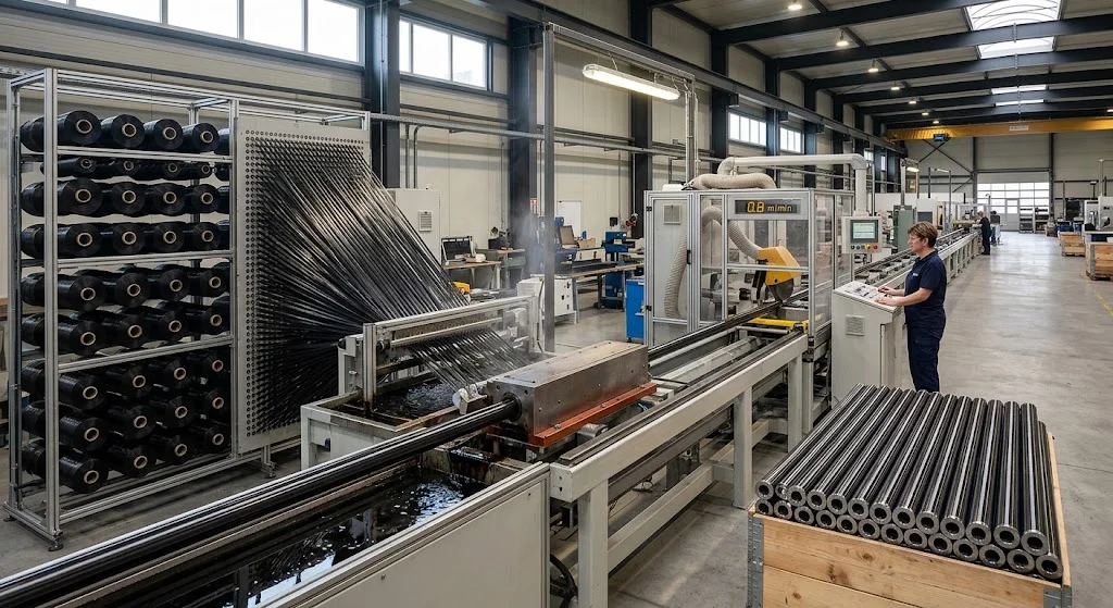
The process is continuous and runs in four stages. First, creels of carbon fiber tow are unwound and guided into a alignment plate that sets the fiber orientation — usually near-unidirectional, with most tows running along the pull axis. Second, the aligned fiber passes through a resin bath (typically epoxy, vinyl ester or phenolic, depending on the application's fire, chemical or temperature requirements) where it is wetted out. Third, the saturated fiber enters a heated steel die — the die geometry defines the final cross-section — where the resin cures as the profile is pulled through at speeds of 0.3 to 1.5 metres per minute. Fourth, a puller grips the cured profile and a flying saw cuts it to the specified length.
Because the fiber is pulled along the axis, the finished profile is nearly unidirectional. Typical fiber volume fraction is 60-70%, giving an axial tensile modulus of 100-150 GPa for standard-modulus fiber and an axial tensile strength of 1200-1800 MPa. Those figures make a pultruded carbon fiber tube roughly four times stiffer and five times stronger per unit weight than an equivalent aluminium tube in the axial direction. The same alignment, however, means transverse and hoop properties are a small fraction of the axial values — the mechanical limit that defines where these profiles can and cannot be used.
Profile Range: What Pultruded Carbon Fiber Shapes Are Available
Pultruded profiles are supplied in a wide standard range, with custom dies available for higher volumes. The common families include:
- Rods: Solid circular cross-sections, typically 2-20 mm diameter. Used for pin axles, antenna masts, robotic arm members and reinforcement bars. High specific strength, but prone to buckling in long slender compression applications.
- Tubes: Hollow circular sections, outside diameters 3-50 mm with wall thicknesses of 0.5-3.0 mm. The workhorse profile for drone frames, sporting equipment, automation shafts and structural spars.
- Rectangular and square tubes: Used where flat mounting surfaces are needed — frame members, enclosure rails, machine guards.
- Angles and channels: L-shaped and C-shaped profiles for stiffening ribs, edge protection and lightweight framing.
- Flat bars and rods with special cross-sections: Including T-sections, I-sections and custom extrusions for specific structural applications.
Stock sizes ship from inventory; custom profiles require a dedicated die, which carries a tooling charge and a minimum run — typically 500-2000 metres depending on the section complexity.
Mechanical Limits Every Designer Should Know
The unidirectional nature of pultruded carbon fiber creates a set of mechanical limits that are consistent across suppliers and material systems. The table below summarizes the key figures and the design consequence of each.
| Property | Typical value | Design consequence |
|---|---|---|
| Axial tensile modulus | 100-150 GPa | Excellent for tension members and stiff spars |
| Axial tensile strength | 1200-1800 MPa | High load capacity along the pull axis |
| Transverse tensile strength | 40-80 MPa | Weak axis — avoid bolt clamp load directly on wall |
| Hoop / radial crush strength | 30-60 MPa | Use sleeves or bushings at bolted joints |
| Torsional stiffness | Governed by thin wall, not fiber | Poor torque capacity — add overwrap if twisting is expected |
| Axial CTE | ~0 to 1 × 10⁻⁶/K | Near-zero thermal growth — ideal for precision structures |
| Transverse CTE | 20-40 × 10⁻⁶/K | Differential expansion across axes — check bonded joints |
Three failure modes dominate in practice. Buckling governs long slender tubes in compression — a 10 mm OD tube with 1 mm wall will buckle far below its material compressive strength if unsupported over a long span. Local crushing at bolt holes and clamp points is the second common failure — the thin unidirectional wall crushes under concentrated bearing load long before the tube reaches its rated tensile capacity. Delamination at cut ends is the third: an unsealed saw cut exposes fiber ends to moisture and impact, and the profile can begin to split along the fiber axis under load. All three are manageable with the right design details, but all three are predictable consequences of the unidirectional fiber architecture.
Design Rules for Pultruded Carbon Fiber Rods and Tubes
A few practical rules cover most pultruded carbon fiber design work:
- Design for the axis: Load the profile in tension, compression or bending along the pull direction. Avoid transverse point loads and concentrated bearing at joints without a spreader.
- Check buckling before strength: For any compression member longer than about 30 times its diameter, Euler buckling will govern before material strength. Use the correct end-condition factor (pinned-pinned = 1.0, fixed-pinned = 0.7, fixed-free = 2.0) and iterate.
- Spread clamp pressure: Use a bonded sleeve, a bushing or a potted insert at every bolted or clamped connection. A M4 bolt directly on a 1 mm wall crushes the tube; the same bolt through an aluminium sleeve distributes the load safely.
- Seal cut ends: Paint, gel coat or epoxy-seal every cut face. An unsealed end in an outdoor structure absorbs moisture, and freeze-thaw cycles can initiate delamination within one season.
- Respect the CTE mismatch: If bonding a pultruded profile to aluminium or steel, design the joint to accommodate 20-40 × 10⁻⁶/K transverse expansion against near-zero axial expansion — a flexible adhesive bond line or a slotted hole usually suffices.
Frequently Asked Questions
What is the difference between pultruded carbon fiber and roll-wrapped carbon fiber tube?
Pultruded tubes are made by pulling fiber continuously through a heated die, producing a nearly unidirectional wall with very high axial stiffness but weak transverse properties. Roll-wrapped tubes are made by wrapping prepreg around a mandrel and curing, which allows multi-directional layups (0/±90) that give better torsional and hoop performance at a higher cost per metre. For pure axial loads — struts, spars, shafts — pultruded is usually the more efficient choice; for applications with significant twisting or radial pressure, roll-wrapped or overwrapped pultruded profiles should be considered.
Can pultruded carbon fiber rods and tubes be drilled, machined and bonded?
Yes, with care. Drill and machine with carbide tooling at moderate speed with dust extraction; back the exit side to prevent splintering of the unidirectional wall. Bond with a two-part epoxy after scuffing and cleaning the surface; a cylindrical sleeve at the bond interface spreads the load and prevents peel. Avoid adhesive bonds loaded purely in peel — the interface strength is much lower than the axial strength of the profile.
What are the standard lengths and tolerances for pultruded carbon fiber profiles?
Stock lengths are typically 1 metre or 2 metres, cut to order. Outside-diameter tolerance on standard pultruded tubes is usually ±0.1-0.2 mm; wall thickness tolerance ±0.1 mm; straightness within 1 mm per metre. Custom lengths are available but may carry a cutting charge. For precision applications — optical benches, metrology arms, robotic end effectors — specify the tighter tolerance band and confirm the supplier's measurement method before ordering.
Conclusion
Pultruded carbon fiber is the most economical route to a very stiff, very light structural profile, and its mechanical limits are direct consequences of the process that makes it: near-unidirectional fiber alignment delivers exceptional axial stiffness and strength, and correspondingly weak transverse, hoop and torsional properties. Designers who load the profile along its axis, check buckling before material strength, spread clamp pressure with sleeves and seal cut ends will get reliable service from these profiles. Designers who ignore the transverse limits will discover them at the joint — usually in the form of a crushed tube wall or a delaminated end.
YongXian supplies pultruded carbon fiber rod, pultruded carbon fiber tube and a full range of standard and custom profiles to customers worldwide. Browse our product range or contact our engineering team with your cross-section, load case and end conditions — we will recommend the stocked size that fits and flag any mechanical limit your design should account for.
Part of topic
Related Articles
- Carbon Fiber Sheet Cutting Service: CNC Routed Parts and Tolerances
- Carbon Fiber Build Plate: 3D Printer Bed Materials Compared
- Carbon Fiber Tube Connector: Joining Methods and Hardware
- Carbon Fiber Tube for PC: Composite Structural Parts in Custom Builds
- 3K Carbon Fiber vs Carbon Fiber: Tow Size, Weave and Mechanical Trade-Offs
- Pultruded Carbon Fiber Tubes: Properties, Standard Sizes and Design Data
Interested in Our Products?
Contact our team for competitive pricing and technical specifications.
Get a QuoteRelated Products
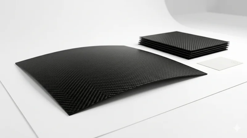
Carbon Fiber Plate — 3K Twill T700 1.5mm
Thin 1.5mm carbon fiber plate with 3K twill weave surface. Lightweight and stiff, commonly used for covers, panels, drone bodies, and applications requiring a premium aesthetic appearance.
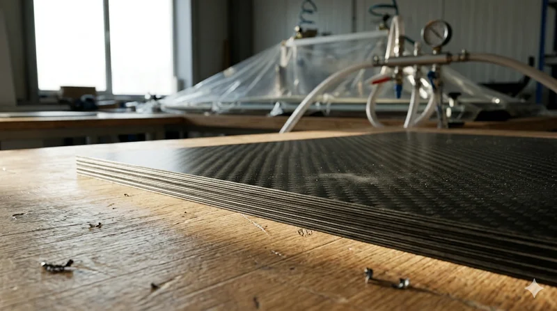
Carbon Fiber Plate — 3K Twill T700 3.0mm
Medium-thickness 3.0mm carbon fiber plate offering significantly higher load capacity while maintaining attractive 3K twill finish. Suitable for structural brackets, reinforcement plates, and load-bearing panels.
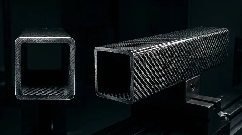
Square Carbon Fiber Tube — 3K Twill T700
Square cross-section carbon fiber tube manufactured with 3K twill weave for torsional strength. Preferred for structural frames, trusses, and support columns where rectangular geometry offers design flexibility.
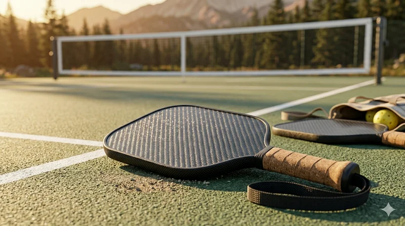
Carbon Fiber Pickleball Paddle
High-performance pickleball paddle with Toray T700 carbon fiber face and polypropylene honeycomb core. Delivers excellent power-to-weight ratio, spin generation, and vibration dampening for competitive play.
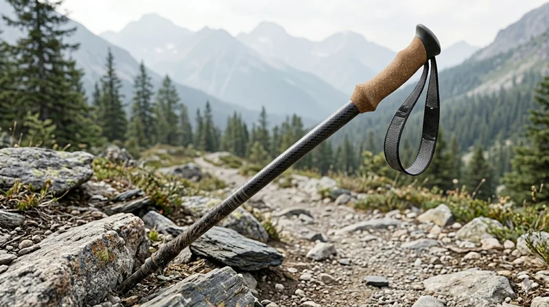
Carbon Fiber Trekking Pole
Lightweight carbon fiber trekking pole manufactured from high-grade carbon fiber tube. Weighs only 160g per pole while providing superior shock absorption and durability for hiking, trail running, and backpacking.