Pultruded carbon-fiber leaf springs are one of the few composite substitutions in a commercial vehicle chassis where the weight saving, the fatigue benefit and the corrosion argument all point the same direction. Where steel multi-leaf packs have carried rear-axle load for a century, a composite spr
Introduction
Pultruded carbon-fiber leaf springs are one of the few composite substitutions in a commercial vehicle chassis where the weight saving, the fatigue benefit and the corrosion argument all point the same direction. Where steel multi-leaf packs have carried rear-axle load for a century, a composite spring does the same job at roughly a fifth of the mass, with no interleaf corrosion mechanism and a fatigue life measured in millions of cycles rather than hundreds of thousands. That combination is why composite leaf springs first reached series production in passenger cars and light commercials, and why heavy-truck and trailer programs are now working through the qualification steps required to follow them.
This article explains how pultruded carbon-fiber leaf springs are manufactured, quantifies the weight, fatigue and corrosion differences against steel multi-leaf and steel parabolic designs, sets out the design boundaries composite springs cannot cross — impact tolerance, bearing stresses at the eyes, and the lower damping that demands a rethink of damper tuning — and describes the test program an OEM or fleet engineer should run before classifying them as production carbon fiber auto parts.
Why Composite Leaf Springs Are Replacing Steel on Rear Axles
Three separate engineering arguments converge on the same part:
- Payload and mass budget: A rear-axle steel multi-leaf pack on a 4x2 rigid truck weighs 45-70 kg per axle. A composite mono-leaf or two-leaf equivalent lands at 8-14 kg. On a vehicle already fighting a payload ceiling, 35-55 kg of sprung-mass reduction per axle is directly saleable payload or a genuine range extension for an electric drivetrain.
- Corrosion and whole-life cost: Steel leaf springs corrode where leaves rub and where road salt collects — the interleaf surfaces and the eye bushings. Composite springs have no interleaf corrosion mechanism. Fleet operators running salted routes report steel spring replacement as a recurring line item; a composite spring removes that line item and the associated shop time.
- Design freedom in the spring rate: A steel pack tunes rate by adding or removing leaves. A composite spring tunes rate through laminate thickness, length, taper and fiber orientation — a continuous design space rather than a stepped one. Parabolic steel springs improved on multi-leaf in exactly this way; composite construction extends the same logic further.
The arguments are strongest where duty cycles are long and mass is expensive: urban delivery fleets, refrigerated trailers, refuse trucks, and battery-electric chassis where every kilogram of suspension mass is a kilogram of battery that did not fit.
Pultruded Carbon-Fiber Leaf Springs: Construction and Layup
Pultrusion is the continuous production route that makes composite leaf springs economically repeatable. The process produces constant-section laminate — strips, plates and profiles — that is then formed into the final spring geometry:
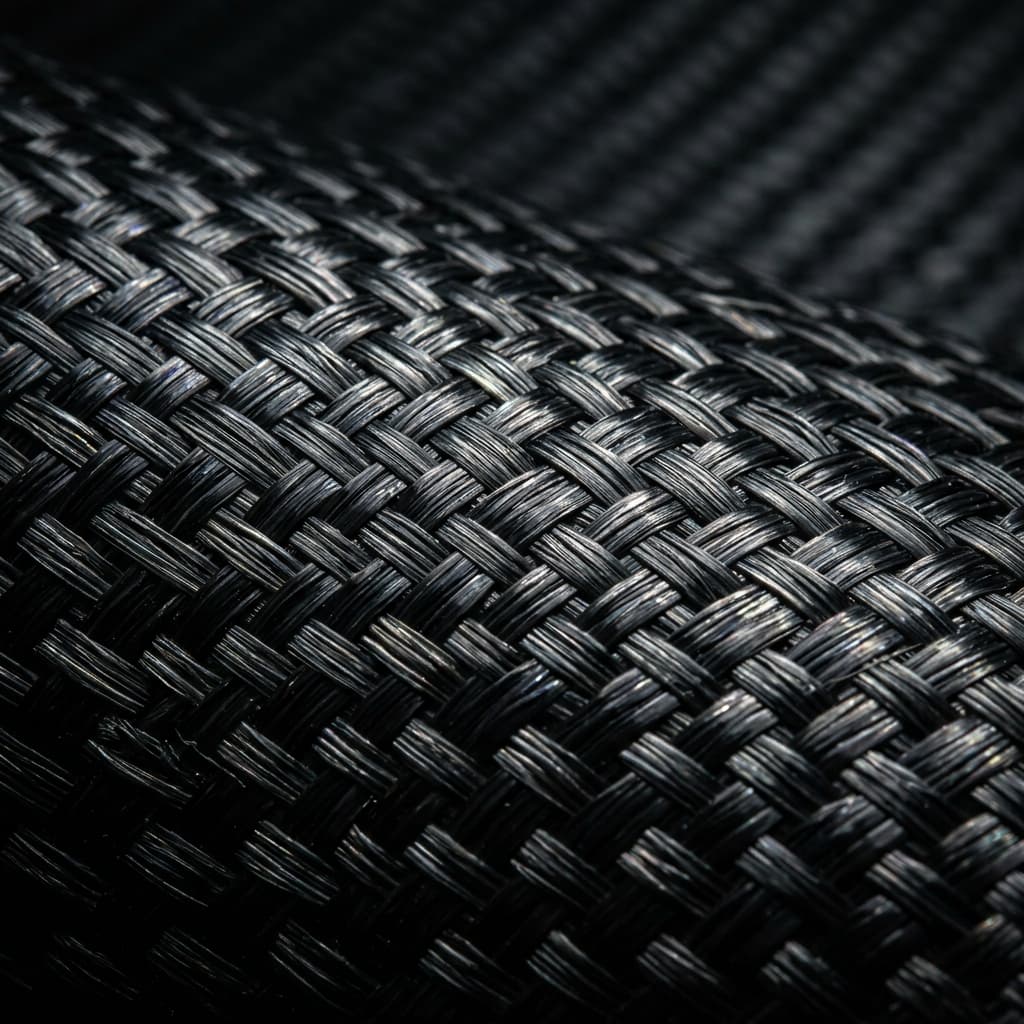
- Fiber architecture: Unidirectional carbon fiber tow dominates the spring, carrying 85-95% of the load along the spring axis. A stitched or woven surface layer adds transverse integrity and protects the UD core during handling and forming. Fiber volume fraction lands at 55-65% after forming.
- Pultrusion of the laminate: Tows are pulled through a resin bath — epoxy for structural springs, vinyl ester where cost dominates — and through a heated die that sets a flat or near-net strip at line speeds of 0.3-1.5 m/min. Axial tensile strength of the cured strip reaches 1200-1800 MPa with a modulus of 100-150 GPa for standard-modulus tow.
- Forming to the leaf geometry: The strip is heated, draped over a mold that defines the camber and the taper, and cured under vacuum or matched-die pressure. Multi-stage curving produces the parabolic profile that lets a single composite leaf replace a five- or seven-leaf steel pack.
- End fittings: The eyes are the highest-stress region and the one place metal returns. Bonded and mechanically retained bushing inserts — steel or aluminum sleeves over an oversized laminate end — transfer load into the chassis without concentrating bearing stress on the composite itself.
The manufacturing consequence matters for buyers: pultruded feedstock is a continuous, well-controlled material, but the curving and curing steps are batch processes. A supplier's ability to hold camber tolerance across a production lot, not their ability to buy carbon fiber, is what separates a suspension-grade source from a profile house.
Weight, Fatigue and Corrosion: Compared Numbers
The table compares typical rear-axle spring sets for a medium-duty commercial vehicle. Values are indicative engineering ranges, not a specific program specification.
| Criterion | Steel multi-leaf | Steel parabolic | GFRP mono-leaf | CFRP pultruded leaf |
|---|---|---|---|---|
| Mass per axle set | 45-70 kg | 25-40 kg | 14-22 kg | 8-14 kg |
| Weight saving vs multi-leaf | Baseline | 35-50% | 60-75% | 75-85% |
| Fatigue life, variable amplitude | 0.3-1.0M cycles | 0.8-1.5M cycles | >1.0M cycles | 1.5-3.0M cycles |
| Corrosion behavior | Interleaf and eye corrosion, coating dependent | Reduced but present | Resistant | Resistant |
| Indicative cost index | 1.0 | 1.3-1.6 | 2.5-3.5 | 4-7 |
| Interleaf damping | High | Medium | Low | Low |
| Packaging height | Tall | Moderate | Low | Lowest |
Two rows deserve comment. The fatigue advantage comes from stress amplitude, not from any inherent magic: a composite spring operating at 25-35% of its static strength sees lower cyclic strain than a steel leaf at 45-60%, and carbon fiber has no fatigue knee below its endurance limit. The damping row is the honest penalty — a multi-leaf pack dissipates energy through interleaf friction, a composite leaf does not, and damper tuning must absorb the difference or ride quality degrades.
Design Boundaries: What Composite Leaf Springs Cannot Do
Composite leaf springs fail in characteristic ways, and a chassis engineer has to design against them rather than discover them on a test track:
- Bearing and bolt load at the eyes: Composite interlaminar and bearing strength is far below its axial tensile strength. Every design uses a metal insert, a wide load-spreading washer, or both. Direct bolt clamping onto bare laminate is the most common self-inflicted failure mode.
- Impact and stone strike: A steel leaf takes a stone strike on the underside and continues in service. A composite leaf can dent or delaminate locally, and that damage site becomes the fatigue initiation point. Underside protection — a bonded wear strip or a sacrificial metal shield — is standard on serious programs.
- Overload and abuse loading: Composite springs have a hard overload limit and little warning before it. Design factors of 2.5-3.0x static design load with a demonstrated deformation recovery are typical acceptance criteria; steel is more forgiving of a single severe overload event.
- Temperature ceiling: Epoxy matrix springs hold properties to roughly 80-120°C glass transition. Exhaust routing and brake heat shields near the spring are a packaging constraint, not an afterthought.
- Repairability: A damaged steel leaf can be replaced leaf by leaf. A damaged composite spring is replaced as a unit, which raises the stakes on damage tolerance and pushes inspection intervals into the maintenance plan.
Pultruded Carbon Fiber in the Wider Suspension System
Leaf springs are rarely the only composite in a modern chassis. Pultruded carbon fiber tubes and profiles also appear in stabilizer bars, trailing arms, drive-shaft tubes and subframe members, and the qualification logic is shared: continuous pultruded feedstock, formed or cut to geometry, with metal interfaces wherever load concentrates. Buyers who already specify pultruded carbon fiber tubes for other chassis parts can often consolidate qualification testing across parts, because the laminate source, resin system and process controls are the same. That consolidation is the practical reason to evaluate carbon fiber leaf springs together with the rest of the composite chassis program rather than as an isolated part change.
Qualification and Testing Path for Production Programs
Turning a composite spring from a prototype into a production carbon fiber auto part means running a defined test matrix:
- Static load to failure: Verify ultimate load and deformation mode, confirming the failure is in the expected region rather than at the eye insert.
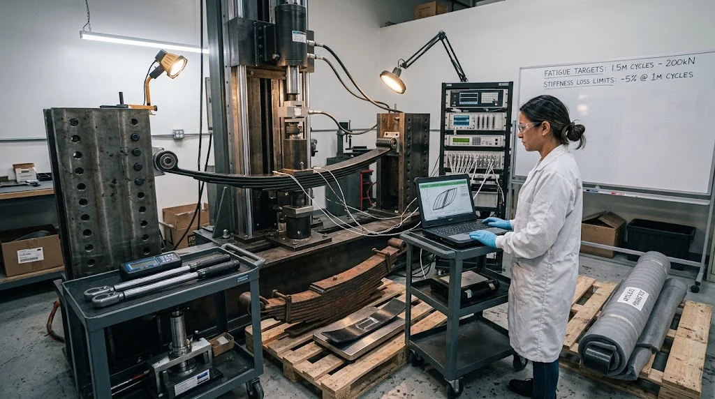
- Variable-amplitude fatigue: Road-load-derived spectra, typically 1.5-3.0 million cycles, with periodic stiffness checks and a defined stiffness-loss rejection limit.
- Corrosion exposure: Salt-spray and thermal-humidity cycling per automotive standards, followed by residual static and fatigue checks — composite springs survive this far better than steel, but the eye inserts must be tested with them.
- Impact damage tolerance: Controlled underside impacts at representative energies, then fatigue continuation to demonstrate damage-tolerance credit or trigger a reject criterion.
- Environmental and aging: UV exposure, fluid resistance, and high-temperature dwell near the glass transition boundary.
- Full-vehicle validation: Proving-ground durability and ride-quality sessions, with damper and anti-roll tuning revisited to absorb the loss of interleaf damping.
The full matrix typically runs 9-18 months. Programs that parallelize it with damper retuning and bushing development compress that timeline meaningfully.
Frequently Asked Questions
How much weight does a pultruded carbon-fiber leaf spring save on a commercial rear axle?
Against a steel multi-leaf pack, 35-55 kg per axle is typical — 45-70 kg of steel replaced by 8-14 kg of composite. Against a steel parabolic pack the saving is smaller, roughly 12-25 kg per axle, because parabolic steel already removes most of the interleaf mass. The economic case is strongest on multi-leaf-to-composite conversions and on battery-electric chassis, where each kilogram saved converts directly into range or payload.
Why use pultrusion instead of compression molding for composite leaf springs?
Pultrusion produces the flat laminate with consistent fiber volume fraction, orientation and void content in a continuous, well-controlled process; forming to the leaf geometry is then a separate, adjustable step. Compression molding of a full spring in one shot is possible with preforms, but it locks fiber architecture into the mold and typically delivers lower fiber volume fraction in the curved regions that carry the most strain. Pultruded-and-formed construction is preferred when the spring rate must be tuned precisely and lot-to-lot consistency is a qualification requirement.
What happens when a composite leaf spring is damaged in service?
Damage tolerance is designed in, not assumed. Underside dents and delaminations are assessed against reject criteria defined during qualification — typically a maximum damaged area and depth at which residual static strength still exceeds the design load with margin. Springs that pass the criterion stay in service with an inspection interval; springs that fail it are replaced as a unit. This is the operational trade: lower mass and longer fatigue life in exchange for unit replacement rather than leaf-by-leaf repair.
Conclusion
Pultruded carbon-fiber leaf springs deliver the rare case where lightweighting, fatigue life and corrosion resistance all improve at once, provided the chassis design respects the material's boundaries — metal inserts at the eyes, underside protection, a hard overload limit, and damper tuning that replaces the damping a multi-leaf pack used to provide free of charge. Where those conditions are met, 75-85% spring-mass reduction and fatigue lives above 1.5 million cycles are achievable on production programs, not laboratory demonstrations.
For chassis and suspension teams evaluating composite springs alongside other carbon fiber auto parts, explore our pultruded carbon fiber tubes, plates and profiles — the same continuous-laminate feedstock used in leaf-spring construction, supplied in stock and custom sections. Contact our engineering team with your spring rate, eye geometry and duty-cycle spectrum, and we will help map a laminate and forming route that fits your program's qualification timeline.
Part of topic
Related Articles
- Carbon Fiber Tube Protector: Edge Guards and Damage Prevention
- Carbon Fiber RC Body: Lightweight Shells for On-Road and Off-Road Cars
- Carbon Fiber FPV Drone Frame: Geometry, Materials and DIY Builds
- Carbon Fibre Drone Frame: UK Buying Guide
- Filament Wound Pressure Vessel: Design, Standards and Manufacturing
- Carbon Fiber Car Parts: Structural vs Cosmetic Components Explained
Interested in Our Products?
Contact our team for competitive pricing and technical specifications.
Get a QuoteRelated Products
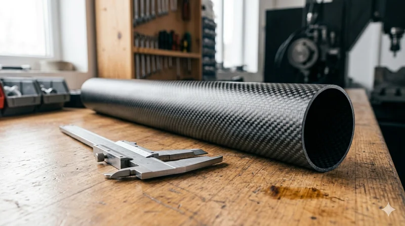
Round Carbon Fiber Tube — 3K Plain Weave T700
Standard round carbon fiber tube manufactured from Toray T700 grade fiber with 3K plain weave. Offers balanced strength and stiffness for general industrial applications including robotics, automation, sports equipment, and aerospace structures.
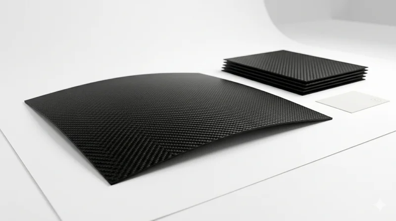
Carbon Fiber Plate — 3K Twill T700 1.5mm
Thin 1.5mm carbon fiber plate with 3K twill weave surface. Lightweight and stiff, commonly used for covers, panels, drone bodies, and applications requiring a premium aesthetic appearance.
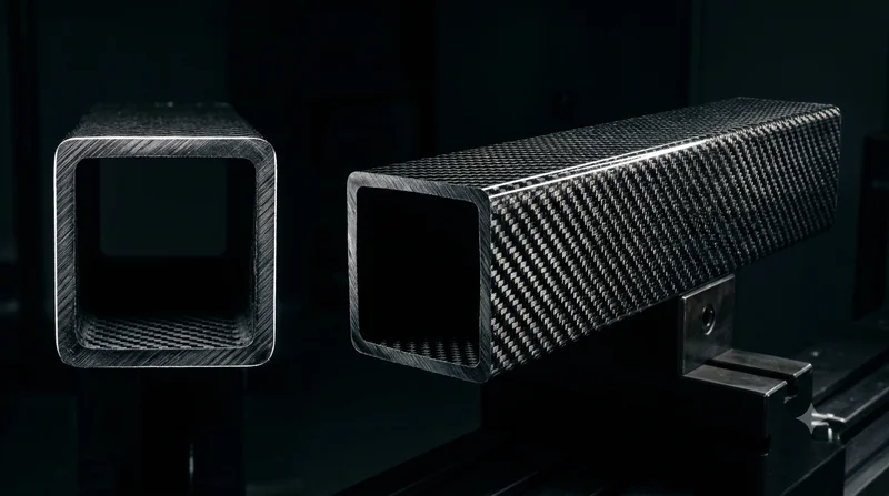
Square Carbon Fiber Tube — 3K Twill T700
Square cross-section carbon fiber tube manufactured with 3K twill weave for torsional strength. Preferred for structural frames, trusses, and support columns where rectangular geometry offers design flexibility.
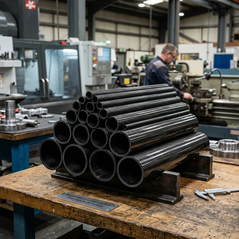
Round Carbon Fiber Tube — 3K Twill
Lightweight and ultra-stiff round tubes ideal for drone frames, robotics, and structural applications.
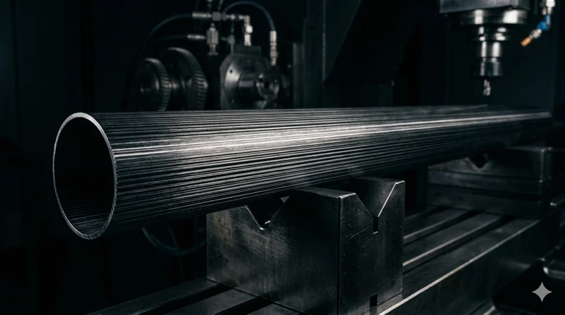
Round Carbon Fiber Tube — UD Unidirectional T700
Unidirectional (UD) round tube with all fibers aligned axially for maximum longitudinal stiffness. Ideal for applications requiring high bending rigidity with minimal weight, such as shafts, struts, and structural reinforcements.