

Modern warships carry radar, communications, and electronic-warfare antennas in plain view — an arrangement that has existed for a century. But those open masts create two problems for naval designers. The first is radar cross section: a lattice of steel, cables, and exposed antennas is
Introduction
Modern warships carry radar, communications, and electronic-warfare antennas in plain view — an arrangement that has existed for a century. But those open masts create two problems for naval designers. The first is radar cross section: a lattice of steel, cables, and exposed antennas is a strong reflector that can dominate a ship's signature. The second is topside weight: every antenna needs its own platform, bracket, and cabling, pushing weight high above the waterline, where it most hurts stability.
The integrated mast answers both problems by enclosing sensors and antennas inside a faceted housing, usually built as a composite sandwich structure. This article explains what integrated masts are, the composite materials that make them possible, how they manage radar and other signatures, and the structural demands of operating for decades in a marine environment.
What an Integrated Mast Is
An integrated mast is a modular, multi-faceted housing that combines radar antennas, communications systems, electro-optical sensors, and navigation equipment into a single enclosed structure. Instead of each sensor being mounted openly on its own platform, the antennas sit inside the housing behind panels of radar-transparent material, and the structure itself is shaped to deflect radar energy away from the source.
Examples in service are growing. Denmark's Iver Huitfeldt-class frigates, commissioned from 2012, proved the concept for NATO, and the United Kingdom's Type 31 frigates follow a similar design lineage. The United States Navy's Zumwalt-class destroyers pair composite deckhouses with integrated radar. Sweden's Visby-class corvettes went further, building the hull and superstructure entirely from carbon fiber sandwich panels to minimize signature. Each program shows the same logic: fewer external protrusions, lower radar cross section, and less weight above the center of gravity.
Composite Materials for Radome and Structure
The materials selection for an integrated mast is dictated by two conflicting requirements: structural strength and radio-frequency transparency. The housing must carry antennas, withstand wind, ice, and shock loads — a structural job well suited to composite sandwich construction — but in front of every radar aperture, the material must let electromagnetic waves pass with minimal loss.
Designers solve this with a hybrid approach:
- Radar-transparent panels: quartz-fiber or E-glass laminates with epoxy resin sit in front of radar apertures. Quartz fiber in particular has a very low dielectric constant and loss tangent, which keeps signal attenuation and distortion minimal.
- Carbon fiber structure: away from the apertures, carbon-fiber-reinforced sandwich panels — carbon skins over foam or honeycomb cores — provide the stiffness and strength while cutting weight.
- Core materials: PVC and PMI foams and Nomex honeycomb provide the lightweight thickness that makes sandwich panels stiff, sized to meet the shell's buckling and impact requirements.
Carbon fiber is electrically conductive, which is precisely why it cannot sit in front of a radar antenna — it reflects rather than transmits. The hybrid layout keeps conductive structure away from the apertures and reserves the transmission path for non-conductive quartz or glass composites.
Signature Management
Signature management is the reason integrated masts exist. The faceted geometry, the enclosing of sensors, and the material choices all contribute to a lower radar cross section:
- Geometry: flat, angled facets reflect radar energy in a few directions instead of scattering it in all directions back to the source.
- Enclosure: sensors that would otherwise be naked reflectors sit inside the housing, removing their direct contribution to the signature.
- Absorbing treatments: radar-absorbing coatings and materials can be added to outer surfaces where needed.
- Integrated apertures: antennas conform to the mast faces rather than protruding, preserving the exterior shape.
Signature reduction is a system-level outcome — no single number describes it fairly — but the integrated approach consistently delivers dramatically lower mast radar cross section than the open layouts it replaces, with published program claims of order-of-magnitude improvements.
Structural and Environmental Demands
An integrated mast is one of the most heavily loaded composite structures in naval service. It is exposed to salt spray, ultraviolet radiation, ice accretion, and the blast and jet exhaust of flight operations; it must resist the shock loads of a near miss; and it must stay watertight for decades without the maintenance access that open platforms offer.
Composite sandwich construction is well suited to that duty:
| Requirement | Traditional Open Steel Mast | Integrated Composite Mast |
|---|---|---|
| Radar cross section | High, from lattice and exposed antennas | Low, from faceted enclosed design |
| Topside weight | Heavy steel structure and brackets | Typically 30-50% lighter sandwich structure |
| Corrosion maintenance | Continuous paint and steel recoat cycles | Composites resist seawater corrosion inherently |
| Sensor environment | Antennas exposed to weather and waves | Protected behind radome panels |
| Electrical behavior | Conductive structure managed for EMC | Conductivity tailored per zone for EMC and lightning |
The critical engineering concerns are moisture ingress at joints, lightning protection, and grounding. Water trapped inside a sandwich panel can freeze and delaminate the skins, so edge sealing and bonded-joint design are decisive. Lightning protection uses diverter strips and conductive mesh integrated into the outer skin and grounded to the ship's hull, mirroring the practice proven on composite aircraft.
Qualification and Testing Before Service
An integrated composite mast cannot go to sea on strength predictions alone; it must be proven. Structural qualification typically combines static strength tests on a full-scale article or critical sub-panels, fatigue testing representative of decades of ship motion and vibration, and shock testing that simulates the underwater blast environment of a near miss. The sandwich panel architecture is tested at the coupon level for edgewise and flatwise properties, moisture uptake, and freeze-thaw cycling, because a panel that traps water will fail where design analysis predicted margin. Whole-mast assembly trials also validate fit, wiring routes, and the access closures that will be opened for maintenance at sea, so that the first installation is also the proven one.
Electrical qualification matters just as much. Radome panels are measured for transmission loss and dielectric properties across the radar bands they protect, both dry and after accelerated salt-fog and water-immersion aging, since water ingress changes the electrical performance before it becomes a structural problem. The result of this combined program is a mast whose mechanical and electromagnetic behavior is documented against the same evidence standard as the warship itself — which is precisely what shipyards and procurement agencies need to approve a composite mast for class service.
Frequently Asked Questions
Does carbon fiber block radar signals?
Yes — carbon fiber is electrically conductive, so it reflects and attenuates radar waves rather than transmitting them. That is why radar apertures in integrated masts are covered with radio-frequency-transparent materials such as quartz fiber or E-glass laminates, while carbon fiber is used elsewhere in the structure. Getting this split right is one of the core design tasks for an integrated mast, and it is why the hybrid structure described above exists.
Can an existing warship be retrofitted with an integrated mast?
Retrofitting is possible but usually expensive. The mast is a major structural element that changes topside weight, the center of gravity, and the cabling and cooling routes of the entire sensor suite, so most integrated mast programs are designed into new hulls. Some navies have replaced individual masts and radar housings on existing ships, but the full signature benefit comes when hull, structure, and sensor layout are designed together from the start.
How does an integrated composite mast survive lightning and salt water?
Lightning protection is built in through diverter strips and a conductive mesh on the outer skin, bonded and grounded to the ship's hull — the same technique certified on composite aircraft. Salt-water durability comes from the material itself: composites are inherently corrosion-resistant, unlike painted steel. The remaining enemy is moisture ingress at joints and edges, which is why edge sealing, bonded joints, and watertight access closures are designed and inspected with the same rigor as the structure itself.
Conclusion
Integrated composite masts have moved from concept to fleet standard because they solve a problem no modern navy can ignore: signature. By enclosing sensors in a faceted, radar-absorbing composite housing, naval designers reduce radar cross section, remove topside weight that hurts stability, and cut the corrosion maintenance burden of steel masts. The materials challenge — balancing radar transparency against structural strength — is well understood and proven in service.
For defense primes, shipyards, and supply-chain buyers, the path from specification to delivered mast runs through dependable composite material supply. Explore our composite material range or contact our technical team to discuss sandwich panels, radome materials, and qualification support for naval programs.
Related Articles
- Carbon Fiber Mooring for Floating Offshore Wind: Fatigue and Corrosion in Deep Water
- Carbon Fiber Bicycle Frame Optimization: Layup Design and Manufacturing for Competitive Racing
- Carbon Fiber CFRP Retrofit for Infrastructure: Bridge and Building Seismic Strengthening
- Carbon Fiber Medical Imaging Equipment: Lightweight Gantry and Couch Structures for MRI/CT
- Carbon Fiber EV Battery Enclosures: Crash Safety and Electromagnetic Shielding Design
- Carbon Fiber Structures for Low-Altitude Economy: UAV Airframes and eVTOL Components
Interested in Our Products?
Contact our team for competitive pricing and technical specifications.
Get a QuoteRelated Products

Carbon Fiber Plate — 3K Twill T700 1.5mm
Thin 1.5mm carbon fiber plate with 3K twill weave surface. Lightweight and stiff, commonly used for covers, panels, drone bodies, and applications requiring a premium aesthetic appearance.

Square Carbon Fiber Tube — 3K Twill T700
Square cross-section carbon fiber tube manufactured with 3K twill weave for torsional strength. Preferred for structural frames, trusses, and support columns where rectangular geometry offers design flexibility.

Carbon Fiber Plate — UD Unidirectional T700
Unidirectional carbon fiber plate with all fibers oriented in a single direction for maximum strength along the fiber axis. Essential for structural reinforcements, splints, and applications where load direction is predictable.

Round Carbon Fiber Tube — UD Unidirectional T700
Unidirectional (UD) round tube with all fibers aligned axially for maximum longitudinal stiffness. Ideal for applications requiring high bending rigidity with minimal weight, such as shafts, struts, and structural reinforcements.
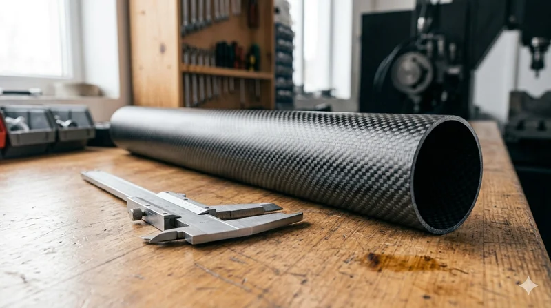
Round Carbon Fiber Tube — 3K Plain Weave T700
Standard round carbon fiber tube manufactured from Toray T700 grade fiber with 3K plain weave. Offers balanced strength and stiffness for general industrial applications including robotics, automation, sports equipment, and aerospace structures.