
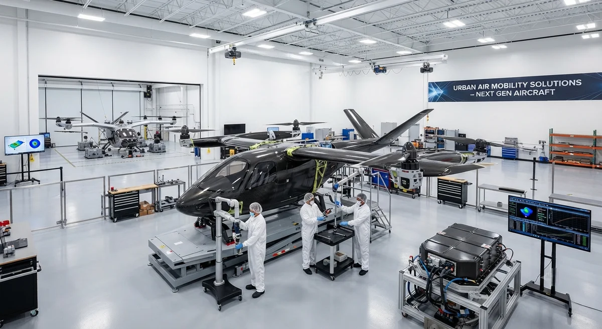
The eVTOL (electric vertical take-off and landing) aircraft market — often referred to as "flying cars" — is projected to require 12,000–18,000 tonnes of carbon fibre annually by 2035 as 9+ aircraft types near certification. This article covers structural design requirements for carbon fiber airframes, rotor systems, battery containment structures, and crashworthiness compliance for B2B suppliers to the eVTOL supply chain.
The eVTOL Revolution: Carbon Fiber at the Core
The convergence of urban air mobility (UAM), advanced electric propulsion, and autonomous flight technology is driving the development of a new class of aircraft — electric vertical take-off and landing (eVTOL) vehicles, popularly termed "flying cars." As of mid-2026, nine distinct eVTOL aircraft types are in advanced certification stages with EASA (European Union Aviation Safety Agency) or the FAA (Federal Aviation Administration), with the first type certifications anticipated in 2027–2028. These vehicles — ranging from 2-passenger personal air vehicles to 5-passenger air taxis — are designed for short-haul urban and suburban missions of 25–200 km, with cruise speeds of 150–300 km/h and maximum take-off weights (MTOW) of 700–3,000 kg.
Carbon fiber composites are not merely a weight-saving option for eVTOL structures — they are an enabling technology. With battery energy density currently at 250–350 Wh/kg (cell level), every kilogram of airframe weight saved translates directly into additional payload capacity or range. Industry analysis by Vertical Integration Consortium (2026) indicates that eVTOL airframes are 70–85% composite by weight — the highest composite percentage of any aircraft category — with carbon fiber/epoxy systems comprising the vast majority of structural components. This article provides B2B suppliers and engineering teams with a comprehensive technical overview of carbon fiber structural requirements for eVTOL aircraft, covering airframe architecture, rotor blade composites, battery containment, crashworthiness, and certification pathways.
eVTOL Airframe Architecture and Carbon Fiber Requirements
Primary Airframe Structure
Most eVTOL designs employ one of three primary structural architectures: (1) wing-and-tilt-rotor (e.g., Joby Aviation S4, Lilium Jet), (2) lift-plus-cruise with separate fixed wings and lift rotors (e.g., Archer Midnight, Beta Technologies ALIA), or (3) multirotor with distributed electric propulsion (e.g., Volocopter VoloCity, EHang EH216-S). Despite architectural differences, all three share common structural requirements driven by the unique eVTOL load spectrum — high cycle counts (10,000–50,000 flight cycles over design life vs 20,000–40,000 for conventional aircraft of similar weight), high peak loads during vertical landing, and crash load cases that combine vertical and horizontal deceleration.
| Airframe Component | Typical Material | Fibre Architecture | Resin System | Typical Mass (kg) | % of Airframe Weight | Key Requirement |
|---|---|---|---|---|---|---|
| Wing box / Main wing spar | IM7 carbon/epoxy unidirectional tape | 0°/±45° quasi-isotropic layup, heavy 0° bias (60-70%) | 177°C cure epoxy (350°F class) | 35–85 | 18–22% | Fatigue life >50,000 cycles, ultimate load factor 5.7g |
| Fuselage / Cabin structure | Intermediate modulus carbon fabric/epoxy | ±45° bias fabric for shear stiffness, ±30°/90° for hoop | 121°C cure epoxy (vacuum-bag-only capable) | 45–110 | 22–28% | Crash energy absorption (10–16 g vertical), occupant protection |
| Boom / Tail structure | Standard modulus carbon/epoxy | Unidirectional with ±45° fabric wrap | 121°C cure epoxy | 8–25 | 4–7% | Stiffness-driven design, flutter margin >15% |
| Rotor blades (lift) | High-modulus carbon/epoxy with foam core | 0° unidirectional spar + ±45° fabric skin | 177°C cure epoxy | 1.5–6.0 per blade | 12–18% | High-cycle fatigue (10⁷–10⁸ cycles), impact resistance (bird strike) |
| Rotor blades (propulsion/cruise) | Carbon/epoxy with hybrid leading edge protection | 0° unidirectional + ±45° fabric + nickel alloy erosion shield | Toughened epoxy (impact-modified) | 0.8–4.0 per blade | 6–10% | Erosion resistance, FOD tolerance, high RPM centrifugal loads |
| Battery containment structure | Carbon/epoxy sandwich (Nomex or foam core) | ±45°/0°/90° fabric facesheets over core | 121°C cure, fire-retardant epoxy | 15–60 | 8–15% | Fire containment (5 min at 1,000°C per RTCA DO-311), crash impact |
| Landing gear / Struts | Carbon/epoxy with aluminium inserts | 0° unidirectional with ±45° wrap | Toughened epoxy | 6–18 | 3–5% | High strain-to-failure, energy absorption (3 m/s descent) |
Rotor Blade Composite Design for eVTOL
Rotor blade design for eVTOL aircraft presents composite material challenges that are distinct from both helicopter main rotors and aircraft propellers. The key differentiating factors are: (1) high cyclic frequency — eVTOL lift rotors operate at 1,500–3,000 RPM with 10,000–50,000 flight cycles, each containing 10⁵–10⁶ rotor revolutions, requiring fatigue endurance beyond 10⁷–10⁸ cycles; (2) variable pitch and RPM — many eVTOL designs use collective and cyclic pitch control for thrust vectoring, imposing complex combined bending-torsion loads on the blade structure; (3) noise constraints — tip speeds are limited to Mach 0.50–0.65 (versus 0.70–0.85 for helicopters) to meet urban noise limits of 55–65 dBA at 100m, driving larger diameter, lower-solidity rotors with specific twist distributions.
Carbon fiber blade construction typically uses a D-spar (closed-section unidirectional carbon/epoxy laminate) that carries the centrifugal and bending loads, with a foam or Nomex honeycomb core aft of the spar to maintain aerodynamic profile. The blade skin is ±45° carbon fabric sized to carry torsional loads from pitch change. Leading edge protection against erosion and foreign object damage (FOD) uses nickel alloy electroformed sheaths, polyurethane coatings, or hybrid Kevlar/carbon overlaminate systems. Blade mass targets for a 7-metre diameter lift rotor are 4–8 kg per blade (including erosion shield), corresponding to a blade solidity of 8–12% and a composite mass efficiency of 0.55–0.65 kg/kW of installed rotor power.
Crashworthiness Requirements for Composite eVTOL Structures
Crashworthiness certification requirements for eVTOL aircraft represent a novel regulatory space. Unlike conventional aircraft (designed for survivable crash loads of 9g forward, 3g vertical, 1.5g lateral per 14 CFR 23.562), or helicopters (designed for 20g vertical drop from 15m per 14 CFR 27.562), eVTOL aircraft must demonstrate occupant protection under a combined loading condition that includes: (1) vertical impact of 10–16g (from a 10–15m autorotation descent with partial power), (2) longitudinal deceleration of 20–30g (forward impact with obstacle), and (3) roll-over protection up to 30° tilt.
Carbon fiber structures present unique crashworthiness challenges compared to metal airframes. While carbon fiber composites offer specific energy absorption (SEA) of 40–60 kJ/kg — 2–3× higher than aluminium (15–25 kJ/kg) — they exhibit brittle failure modes without the progressive crumpling of ductile metals. Crashworthy carbon fiber designs for eVTOL therefore employ several strategies:
- Triggered crush zones: Proximity to the fuselage, carbon/epoxy tubes and sine-wave web structures are designed with geometric triggers (chamfered edges at 45–60°, stress concentration holes, or ply drop-offs) that initiate progressive crushing. The crush front propagates through the composite by a combination of fibre fracture, matrix cracking, inter-ply delamination, and friction between crushed fragments — achieving stable crush loads of 80–150 kN per metre of crush front width at a steady crush stress of 80–150 MPa.
- Hybrid metallic-composite subfloor: The lower 150–300 mm of the cabin structure combines carbon fibre sandwich panels with aluminium or titanium energy absorbers. The metal components provide ductile energy absorption at high strain rates (10³–10⁴ s⁻¹) while the carbon fibre components provide structural stiffness and cabin containment. The Joby Aviation S4 uses this approach with aluminium honeycomb sandwich in the lower fuselage keel beam area.
- Composite crush tube landing gear: The landing gear struts are designed as energy-absorbing composite tubes that crush progressively under vertical landing loads. Each tube is designed to absorb 3–8 kJ of impact energy with a stroke of 200–400 mm, limiting peak deceleration at the occupant seat rail to <16g. Post-crash inspection is visual-only — replaced if any sign of crush trigger activation is observed.
- Battery containment crash protection: The battery pack (typically 50–150 kWh located in the wing root or cabin floor) is enclosed in a carbon/epoxy sandwich structure with 15–30 mm thick facesheets designed to maintain structural integrity under 30g forward impact and 20g vertical impact without breach of the battery cell containment. The structure must also meet RTCA DO-311 thermal runaway containment requirements — maintaining battery pack integrity for at least 5 minutes when exposed to a 1,000°C propane torch flame on any external surface, without flame penetration into the battery volume.
Materials and Process Selection for eVTOL Production
| Component | Process | Cycle Time | Tooling Material | Annual Volume Range | Supplier Qualification Timeline |
|---|---|---|---|---|---|
| Wing box / Spars | Automated fibre placement (AFP) + autoclave cure | 8–16 hours | Invar steel or carbon composite tooling | 500–2,000 sets/year | 18–24 months |
| Fuselage panels | Hand or AFP layup + vacuum bag only (VBO) cure | 6–12 hours | Aluminium or composite (low-CTE) | 1,000–5,000 sets/year | 12–18 months |
| Rotor blades (lift) | Compression moulding with rubber bladder | 2–4 hours per blade | Steel or aluminium matched dies | 4,000–20,000 blades/year | 18–24 months |
| Rotor blades (propulsion) | Injection-compression moulding (short-fibre CF/PEEK) | 3–8 minutes | Steel injection mould tool | 20,000–100,000 blades/year (high rate) | 12–18 months |
| Battery containment | Compression moulding with prepreg | 20–45 minutes | Steel or cast aluminium | 10,000–50,000 units/year | 12–18 months |
| Interior furnishing | Thermoforming (CF/PA or CF/PEKK organosheet) | 2–5 minutes per part | Aluminium or composite stamping tools | 50,000–200,000 parts/year | 6–12 months |
Certification Compliance for Composite eVTOL Structures
EASA and FAA certification of composite eVTOL airframes follows the "Special Condition VTOL" framework (EASA SC-VTOL, published 2020, amended 2024) and FAA 14 CFR Part 23 Amendment 64 (commuter/utility category, applicable to eVTOL). Key composite-specific certification requirements include:
- Structural substantiation per SC-VTOL Book 1, Section 5: Static strength, fatigue, and damage tolerance demonstration for all composite primary and secondary structures, using element, subcomponent, and full-scale testing. "Building block" approach requires minimum 3 element-level tests per material system, 2 subcomponent tests per structural region, and 1 full-scale static and 1 fatigue test per aircraft type. Composite allowables must be developed using A-STAND or CMH-17 methodology with B-basis allowable values (90% confidence, 95% survival probability).
- Damage tolerance and barely visible impact damage (BVID): Composite structures must demonstrate the ability to withstand a 100 J impact (representative of tool drop, hail strike at cruise speed, or ground handling collision) without the damage growing to critical size between inspection intervals. Typical inspection intervals for eVTOL composite structures are 300–600 flight hours (for structural inspections) and 6,000–12,000 flight hours (for major structural inspections).
- Lightning strike protection: All composite airframes require embedded conductive meshes (expanded copper foil, aluminium flame spray, or interwoven nickel-coated carbon fibre tows) for lightning current conduction (Zone 1A: 200 kA peak current per SAE ARP 5412) and arc prevention at fastener locations. Typical composite LSP adds 0.8–1.5 kg/m² of airframe surface area and must be demonstrated at the coupon level (waveform A, B, C, D per SAE ARP 5416) and full-scale level.
- Material qualification and process control: All composite materials must be qualified per a specification agreed with the certification authority (typically referencing SAE AMS or Hexcel/Solvay product specifications). Process specifications must cover storage (shelf life/outlife per the prepreg section above), layup (autoradiograph or laser projection verification for ply orientation), cure (temperature, pressure, time, vacuum level — all traceable via electronic cure records), non-destructive inspection (ultrasonic C-scan per ASTM E2580 or phased array per ASTM E2669 with reject criteria for delamination >5 mm diameter, porosity >2%, or disbond >10 mm from edge), and repair (bonded or bolted repair procedures per SRM).
Frequently Asked Questions
Q: How does carbon fiber usage in eVTOL differ from conventional aircraft or helicopters?
A: eVTOL aircraft use carbon fiber at a significantly higher percentage (70–85% by structural weight) than either conventional aircraft (Boeing 787: 50%, Airbus A350: 53%) or helicopters (typically 40–60% for modern rotorcraft). The higher composite fraction is driven by three factors: (1) weight sensitivity — every kilogram saved extends range by approximately 0.8–1.2 km for a typical 4-passenger eVTOL, making weight reduction more valuable than for commercial transports where fuel fraction dominates; (2) high cycle count — eVTOLs are designed for 10,000–50,000 flight cycles (vs 20,000–40,000 for equivalent-weight aircraft), requiring outstanding fatigue resistance that carbon fiber provides naturally vs aluminium; (3) distributed electric propulsion — the multiple small rotors impose complex dynamic loads that are best managed through the design flexibility of composite tailoring. Additionally, eVTOL carbon fiber is predominantly intermediate modulus grade (290–350 GPa) rather than the standard modulus (230–240 GPa) common in automotive composites, driven by the higher stiffness requirements for flutter-free rotor blades and thin aerofoil wing sections.
Q: What are the main barriers to scaling eVTOL composite production from hundreds to tens of thousands of aircraft per year?
A: Four key barriers exist: (1) Autoclave bottleneck — current eVTOL airframe manufacturing relies on autoclave-cured prepregs with cycle times of 6–16 hours per cure. For production volumes of 500+ aircraft per year, this requires 8–20 autoclaves at $1.5–5 million each, representing $12–100 million in capital expenditure. Out-of-autoclave (OOA) and vacuum-bag-only (VBO) prepreg systems are under development but currently lack the fatigue databases and certification pedigree of autoclave-cured systems. (2) AFP deposition rates — automated fibre placement of eVTOL wing boxes (20–40 m² per wing) at current speeds of 15–30 kg/hour requires 2–4 hours per wing panel; rates must increase to 50–100 kg/hour for volumes exceeding 2,000 aircraft/year. (3) Rotor blade production — each eVTOL requires 6–16 rotor blades, each of which is currently compression moulded with 2–4 hour cycle times in dedicated matched tooling. For 10,000 blades/year, this requires 60–100 mould sets and corresponding press capacity. Blade injection-compression moulding in thermoplastics (CF/PEEK or CF/PEKK) offers 3–8 minute cycles but requires significant material and process qualification effort. (4) Supply chain maturity — the eVTOL supply chain for composite raw materials (particularly IM-grade carbon fibre in aerospace-qualified forms) and semi-finished goods (prepregged fabrics with certified tack and outlife specifications) must scale in lockstep with aircraft production rates.
Q: What certification timeline should B2B suppliers expect for eVTOL composite components?
A: The certification timeline for a carbon fiber component supplier to a new eVTOL programme typically follows this path: Months 1–6 — Material selection and preliminary allowables generation (500–1,000 coupon tests per material system). Months 6–18 — Subcomponent testing with supplier-fabricated test articles (100–300 components tested through static, fatigue, damage tolerance, and environmental conditioning per RTCA DO-160). Months 12–24 — Full-scale airframe static and fatigue testing support (supplier provides production-representative components). Months 18–30 — Production process qualification (PQR), including first article inspection (FAI) per SAE AS9102, NDT procedure validation, and production rate demonstration at 150% of target rate. Months 30–36 — Continued airworthiness support and in-service data collection. For an existing certified material system (e.g., Hexcel 8552/IM7) applied to a new eVTOL geometry, the timeline can be compressed to 18–24 months. For a new material system or novel process (e.g., rapid-cure prepreg or thermoplastic), 36–48 months is more realistic.
Q: What are the key differences between eVTOL composite structures and automotive carbon fiber in high-volume production?
A: Despite superficial similarity (both use carbon fiber/epoxy in structural applications), eVTOL and automotive composites differ in several critical respects: (1) Qualification pedigree — eVTOL requires aerospace-level material allowables (B-basis, thousands of coupon tests across temperature and moisture conditions) vs automotive's project-specific validation (hundreds of tests at room temperature dry). (2) Defect tolerance — eVTOL structures require NDT (ultrasonic C-scan or phased array) on 100% of primary structure bondlines and laminates, with reject criteria for porosity >2%, delaminations >5 mm, and disbonds >10 mm from edges. Automotive accepts visual-only inspection for many structural components. (3) Traceability — eVTOL requires material lot traceability from fiber precursor through final cure, with all process parameters (temp, pressure, vacuum, time) recorded in an electronic birth certificate for every part. Automotive typically requires batch-level traceability only. (4) Material cost tolerance — eVTOL can absorb intermediate modulus carbon fiber at $45–70/kg; automotive pressure vessel applications target $18–28/kg standard modulus fiber, and automotive body panels target $12–18/kg for large-volume applications. (5) Certification inertia — once an eVTOL composite design is certified, changing material grade or process parameter requires re-qualification costing $500,000–2 million and taking 6–12 months. Automotive production changes are typically validated through a change management process costing $10,000–100,000 over 1–3 months.
Conclusion
Carbon fiber composites are not merely an option for eVTOL aircraft structures — they are the structural material that makes the flying car concept commercially viable. With airframe composite content of 70–85%, each eVTOL aircraft represents a carbon fiber demand of 150–500 kg of intermediate modulus material per unit, translating to a total addressable market of 12,000–18,000 tonnes annually by 2035 at projected production rates of 2,000–4,000 aircraft per year. For B2B carbon fiber suppliers and composite fabricators, the eVTOL market offers exceptional growth — but also demands exceptional technical capability in aerospace-quality manufacturing, certification familiarity with EASA SC-VTOL and FAA Part 23 frameworks, and investment in automated production processes (AFP, compression moulding, thermoplastic forming) that can scale from hundreds to tens of thousands of structural components annually. Companies that build these capabilities now, during the certification phase of the first eVTOL types, will be positioned as preferred suppliers for the production ramp that will follow certification between 2028 and 2032.
Related Articles
- Carbon Fiber Mooring for Floating Offshore Wind: Fatigue and Corrosion in Deep Water
- Carbon Fiber Bicycle Frame Optimization: Layup Design and Manufacturing for Competitive Racing
- Carbon Fiber CFRP Retrofit for Infrastructure: Bridge and Building Seismic Strengthening
- Carbon Fiber Medical Imaging Equipment: Lightweight Gantry and Couch Structures for MRI/CT
- Carbon Fiber EV Battery Enclosures: Crash Safety and Electromagnetic Shielding Design
- Carbon Fiber Structures for Low-Altitude Economy: UAV Airframes and eVTOL Components
Interested in Our Products?
Contact our team for competitive pricing and technical specifications.
Get a QuoteRelated Products

Carbon Fiber Plate — 3K Twill T700 1.5mm
Thin 1.5mm carbon fiber plate with 3K twill weave surface. Lightweight and stiff, commonly used for covers, panels, drone bodies, and applications requiring a premium aesthetic appearance.

Square Carbon Fiber Tube — 3K Twill T700
Square cross-section carbon fiber tube manufactured with 3K twill weave for torsional strength. Preferred for structural frames, trusses, and support columns where rectangular geometry offers design flexibility.

Carbon Fiber Plate — 3K Twill T700 3.0mm
Medium-thickness 3.0mm carbon fiber plate offering significantly higher load capacity while maintaining attractive 3K twill finish. Suitable for structural brackets, reinforcement plates, and load-bearing panels.

Carbon Fiber Plate — UD Unidirectional T700
Unidirectional carbon fiber plate with all fibers oriented in a single direction for maximum strength along the fiber axis. Essential for structural reinforcements, splints, and applications where load direction is predictable.
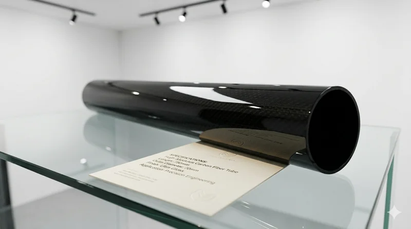
High Modulus Round Carbon Fiber Tube — M40
High modulus round tube manufactured with M40 grade fiber (tensile modulus 400 GPa). Designed for applications where maximum stiffness-to-weight ratio is critical, such as optical systems, precision machinery, and aerospace structures.