
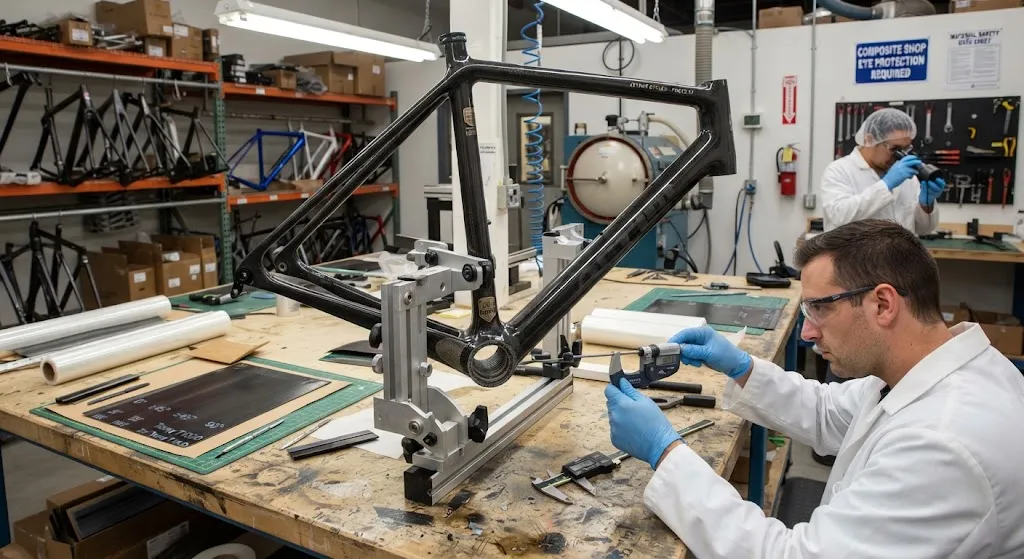
Carbon fiber bicycle frame optimization represents the intersection of material science and competitive cycling performance, where every gram of weight and every Newton-meter of stiffness directly translates to racing advantage. Modern professional racing framesets weigh between 680-900 grams, a dra
Introduction
Carbon fiber bicycle frame optimization represents the intersection of material science and competitive cycling performance, where every gram of weight and every Newton-meter of stiffness directly translates to racing advantage. Modern professional racing framesets weigh between 680-900 grams, a dramatic reduction from the 1,200-1,500 gram aluminum frames that dominated the peloton just fifteen years ago. This weight reduction, combined with precisely tuned lateral stiffness for power transfer and vertical compliance for rider comfort, makes carbon fiber the undisputed material of choice for competitive cycling.
However, achieving these performance targets requires far more than simply wrapping tubes in carbon fiber. Frame manufacturers must optimize fiber orientation at every point in the structure, select appropriate resin systems for impact resistance, and design tube profiles that balance aerodynamics with structural integrity. This article examines the engineering principles behind carbon fiber bicycle frame optimization, from laminate layup theory through tube molding processes, providing the technical foundation for understanding what separates a $500 carbon frame from a $5,000 race-winning machine.
Laminate Design and Fiber Orientation Strategy
The foundation of carbon fiber bicycle frame optimization lies in understanding how fiber orientation affects mechanical properties in each direction. A unidirectional carbon fiber ply provides maximum stiffness and strength along the fiber axis (0 degrees), but offers minimal resistance to loads perpendicular to the fiber. By stacking multiple plies at different angles, engineers create a laminate with tailored directional properties that match the specific loading conditions at each location in the frame.
| Fiber Orientation | Primary Stiffness Direction | Typical Frame Location | Contribution to Performance |
|---|---|---|---|
| 0 degrees (longitudinal) | Axial tension/compression | Down tube, top tube walls | Bending stiffness for pedaling efficiency |
| ±45 degrees | Torsional shear | Head tube, bottom bracket shell | Torsional rigidity for steering precision |
| 90 degrees (hoop) | Radial compression | Seat tube, chainstay junctions | Crushing resistance at clamp points |
| ±30 degrees | Combined loading | Seatstay to seat tube junction | Impact distribution and fatigue resistance |
A typical high-performance racing frame uses 200-400 individual ply cuts, with fiber orientations ranging from -45 to +90 degrees. The layup schedule varies significantly across the frame: the down tube near the bottom bracket uses predominantly 0-degree fibers (60-70% of total plies) for maximum pedaling stiffness, while the head tube region uses a higher proportion of ±45-degree fibers (40-50%) for torsional resistance during aggressive cornering. This variable fiber architecture is what distinguishes an optimized carbon frame from a simple filament-wound tube.
Tube Shaping and Profile Optimization
Beyond fiber orientation, tube cross-sectional shape plays a critical role in frame performance. Modern carbon bicycle frames rarely use simple round tubes; instead, engineers design complex profiles that optimize the balance between stiffness, weight, and aerodynamic drag. The three primary tube shapes used in contemporary racing frames each serve distinct structural purposes.
- Oversized rectangular profiles (down tube): Deep-section rectangular or trapezoidal profiles increase the second moment of area in the vertical plane, providing 15-25% greater lateral stiffness compared to round tubes of equivalent weight. The down tube on a professional racing frame typically measures 55-70mm wide by 65-85mm tall.
- Tapered head tube profiles: The transition from a 1-1/8 inch upper bearing to a 1-1/2 inch lower bearing creates a conical profile that distributes steering loads more effectively, reducing stress concentrations by 30-40% compared to straight 1-1/8 inch head tubes.
- Aerofoil seat tube profiles: Kamm-tail or truncated airfoil seat tubes reduce aerodynamic drag by 8-15% compared to round profiles, while maintaining equivalent bending stiffness. The seat tube profile directly affects frame drag, which accounts for approximately 10-15% of total bicycle aerodynamic resistance.
The challenge of tube shaping lies in maintaining consistent wall thickness during the molding process. Carbon fiber prepreg sheets must conform to complex double-curvature surfaces without wrinkling, bridging, or creating resin-rich areas. Advanced manufacturers use computational draping simulations to predict fiber placement accuracy and optimize blank shapes before committing to production tooling.
Manufacturing Processes and Quality Control
The manufacturing process for a carbon bicycle frame involves multiple critical steps, each introducing potential quality variations that must be controlled to achieve consistent performance. The three primary manufacturing approaches each offer distinct advantages for different frame segments and production volumes.
Bladder molding is the most common process for complex junctions (bottom bracket, head tube, seat tube cluster), where an internal inflatable bladder compacts the laminate against the mold surface under 6-8 bar pressure. Prepreg layup in female molds produces the highest surface finish quality but requires precise temperature control (120-140 degrees Celsius) and cure cycle optimization. Automated fiber placement (AFP) is emerging for high-volume production, with deposition rates of 0.5-1.5 kg per hour enabling consistent ply placement with minimal manual intervention.
Quality control in carbon bicycle frame manufacturing focuses on three measurable parameters: dimensional accuracy (tube alignment within plus or minus 0.5mm), void content (less than 2% for structural integrity), and fiber volume fraction (55-65% for optimal strength-to-weight ratio). Non-destructive testing using ultrasonic scanning or flash thermography identifies delaminations, porosity, and fiber misalignment before frames reach the customer.
Frequently Asked Questions
How does carbon fiber frame stiffness affect pedaling efficiency?
Frame stiffness, particularly lateral stiffness at the bottom bracket, directly affects power transfer efficiency. When a rider applies 400 watts of pedaling force, a frame with 85 N/mm lateral stiffness at the bottom bracket wastes approximately 1-2% of that energy in frame flex, while a frame with 120 N/mm stiffness wastes less than 1%. For a professional cyclist producing 350 watts over a four-hour stage race, this difference represents 14-28 watt-hours of energy saved—equivalent to 200-400 meters of additional distance at the finish. However, excessively stiff frames transmit road vibrations to the rider, increasing fatigue. The optimal stiffness range for competitive racing is 80-120 N/mm lateral at the bottom bracket, balanced with 30-50 mm deflection under 80 kg rider weight for vertical compliance.
What wall thickness variation is acceptable in a carbon bicycle frame?
Aerospace-grade carbon bicycle frames maintain wall thickness variations of plus or minus 0.1mm from the design specification. Typical wall thickness ranges from 0.4mm in high-stress junction zones (bottom bracket, head tube) to 1.2mm in tube mid-sections. Wall thickness below specification reduces strength by the square of the thickness ratio—a 0.1mm reduction from 0.6mm nominal represents a 31% strength loss. Excessive thickness adds weight without proportional strength gains. Leading manufacturers use ultrasonic thickness gauging to verify wall thickness at 20-30 measurement points per frame, ensuring compliance before painting and assembly.
Can carbon fiber frames be repaired after crash damage?
Yes, carbon bicycle frames can be professionally repaired for most impact damage scenarios, provided the repair zone does not exceed 15% of total frame surface area and the damage does not compromise the bottom bracket or head tube structural integrity. Professional repair involves removing damaged material, rebuilding with matching carbon fiber plies in the original orientation, vacuum bag consolidation, and oven cure at the original specification temperature. Repaired frames typically recover 90-95% of original strength and stiffness. However, repair is not recommended for damage that extends more than 50mm along the down tube or top tube, as the structural continuity of the main load path may be compromised beyond recovery.
Conclusion
Carbon fiber bicycle frame optimization is a sophisticated engineering discipline that balances fiber orientation, tube geometry, wall thickness, and manufacturing process control to achieve the performance targets demanded by competitive cycling. The difference between a mass-market carbon frame and a race-winning machine lies not in the raw material, but in the precision of the laminate design and the consistency of the manufacturing process. For cyclists evaluating frame options, understanding these engineering principles provides the foundation for informed purchasing decisions.
For manufacturers and frame designers seeking high-quality carbon fiber materials and technical support, explore our complete carbon fiber product range, or contact our engineering team to discuss material specifications for bicycle frame applications.
Part of topic
Related Articles
- Carbon Fiber Mooring for Floating Offshore Wind: Fatigue and Corrosion in Deep Water
- Carbon Fiber CFRP Retrofit for Infrastructure: Bridge and Building Seismic Strengthening
- Carbon Fiber Medical Imaging Equipment: Lightweight Gantry and Couch Structures for MRI/CT
- Carbon Fiber EV Battery Enclosures: Crash Safety and Electromagnetic Shielding Design
- Carbon Fiber Structures for Low-Altitude Economy: UAV Airframes and eVTOL Components
- Carbon Fiber Satellite Structures: Dimensional Stability for Space Environment Cycling
Interested in Our Products?
Contact our team for competitive pricing and technical specifications.
Get a QuoteRelated Products

Carbon Fiber Plate — 3K Twill T700 1.5mm
Thin 1.5mm carbon fiber plate with 3K twill weave surface. Lightweight and stiff, commonly used for covers, panels, drone bodies, and applications requiring a premium aesthetic appearance.

Carbon Fiber Plate — 3K Twill T700 3.0mm
Medium-thickness 3.0mm carbon fiber plate offering significantly higher load capacity while maintaining attractive 3K twill finish. Suitable for structural brackets, reinforcement plates, and load-bearing panels.

Square Carbon Fiber Tube — 3K Twill T700
Square cross-section carbon fiber tube manufactured with 3K twill weave for torsional strength. Preferred for structural frames, trusses, and support columns where rectangular geometry offers design flexibility.

Carbon Fiber Plate — UD Unidirectional T700
Unidirectional carbon fiber plate with all fibers oriented in a single direction for maximum strength along the fiber axis. Essential for structural reinforcements, splints, and applications where load direction is predictable.

Round Carbon Fiber Tube — UD Unidirectional T700
Unidirectional (UD) round tube with all fibers aligned axially for maximum longitudinal stiffness. Ideal for applications requiring high bending rigidity with minimal weight, such as shafts, struts, and structural reinforcements.