
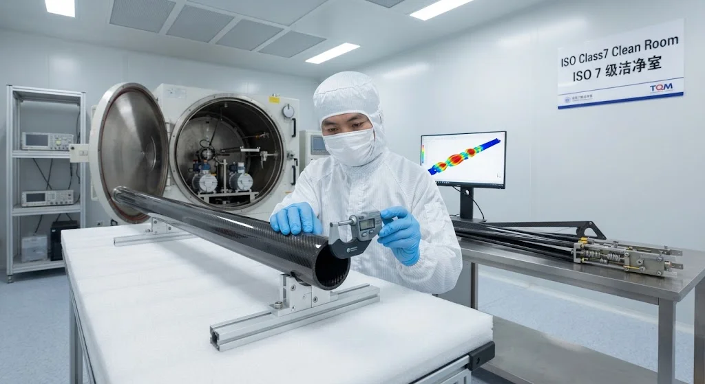
Modern communication, Earth observation, and scientific satellites increasingly rely on deployable structures to achieve the antenna apertures, sensor baselines, and solar collection areas required for their missions. A deployable structure is any mechanical system that transitions from a compact st
Introduction
Modern communication, Earth observation, and scientific satellites increasingly rely on deployable structures to achieve the antenna apertures, sensor baselines, and solar collection areas required for their missions. A deployable structure is any mechanical system that transitions from a compact stowed configuration during launch to an extended operational configuration in orbit. The structural demands on these systems are extreme: they must survive the intense vibration and acoustic loads of launch (typically 10-15 g RMS), deploy reliably after months or years of dormancy in the harsh thermal-vacuum environment of space, and then maintain precise dimensional stability for the satellite's 10-20 year operational life.
Carbon fiber reinforced polymers offer a unique combination of properties that make them the dominant material for satellite deployable structures. Specific stiffness (modulus divided by density) of CFRP is 80-120 GPa/(g/cm³), approximately 7-10 times that of aluminum and 15-20 times that of steel. The coefficient of thermal expansion (CTE) of certain CFRP layups can be tailored to near-zero values (±0.5 × 10⁻⁶/°C), critical for maintaining antenna pointing accuracy as the satellite cycles between sunlight and eclipse. Dimensional stability after cure — characterized by post-cure creep and moisture desorption — is superior to metals, ensuring that deployed structures maintain their designed geometry throughout the mission. This article examines the engineering of carbon fiber deployable structures for satellite applications.
Deployable Boom Types and Configurations
Satellite deployable booms use several structural configurations, each optimized for specific mission requirements:
- Tubular booms (lenticular and C-rolled): Thin-walled carbon fiber tubes that deploy from a flattened stowed state by elastic restoring forces. Lenticular cross-sections (two curved lobes) provide higher stiffness than circular tubes of equivalent weight. These are the most common deployable boom type, used for gravity-gradient boom, magnetometer booms, and antenna mast applications.
- Triangular lattice booms (STEM): Storable Tubular Extendible Members that use a thin carbon fiber composite strip wound into a flat coil for storage and deployed into a triangular cross-section tube. STEM booms achieve deployment lengths of 10-50 meters and are used for large antenna reflector supports and scientific instrument booms.
- Backrollable booms: Composite tubes designed to roll up around a drum for storage and deploy by unrolling. These are used where very long deployment lengths (>10 m) are needed with controlled deployment speed.
- Articulated boom assemblies: Multiple carbon fiber tube segments connected by hinges and latches, deploying sequentially. Used for complex boom geometries that require specific deployed angles or multi-axis articulation.
The choice of boom configuration depends on deployment length, stiffness requirements, stowed volume constraints, and the deployment environment. For communications satellites requiring antenna mast deployment of 3-8 meters, tubular carbon fiber booms with lenticular or circular cross-sections are the standard solution.
Material Selection for Space Deployable Structures
Space-grade carbon fiber materials for deployable structures must meet stringent requirements beyond mechanical performance:
| Property | Requirement | Typical CFRP Value | Rationale |
|---|---|---|---|
| Specific stiffness | >80 GPa/(g/cm³) | 80-120 GPa/(g/cm³) | Maximize deployed natural frequency |
| CTE (through-thickness) | <±1 × 10⁻⁶/°C | ±0.5 × 10⁻⁶/°C (tailored layup) | Thermal dimensional stability |
| Outgassing (ASTM E595) | TML <1.0%, CVCM <0.1% | TML 0.2-0.5%, CVCM <0.05% | Prevent contamination of optics |
| Radiation resistance | No degradation to 100 krad | Minimal property change to 500 krad | 15-20 year LEO/MEO environment |
| Mission life | 10-20 years | Negligible creep at room temperature | Long-term dimensional stability |
High-modulus (HM) or ultra-high-modulus (UHM) pitch-based carbon fibers are preferred for deployable structures due to their superior CTE characteristics and higher modulus. PAN-based fibers offer higher strength but lower modulus and less favorable CTE. The matrix system is typically a space-qualified epoxy with low outgassing properties, or cyanate ester for applications requiring extremely low moisture absorption and dimensional stability.
Deployment Mechanisms and Testing
Reliable deployment is the single most critical requirement for satellite deployable structures. The deployment mechanism must work perfectly after months or years of dormancy in space, with no opportunity for manual intervention. Key deployment mechanisms include:
- Spring-loaded deployment: Torsion or coil springs stored in the boom hinge provide the deployment force. The spring energy is carefully sized to overcome friction and provide controlled deployment acceleration. Typical deployment times range from 30 seconds to 5 minutes depending on boom length.
- Shape memory alloy (SMA) actuators: Nickel-titanium SMA hinges that deploy when heated by electrical current. Provides reliable, repeatable deployment with no mechanical spring wear. Used in high-reliability missions.
- Motorized deployment: Small DC motors with gear reducers drive the boom extension through a lead screw or cable drive. Allows controlled deployment speed, hold-and-retract capability, and deployment monitoring. Used for large, heavy booms.
- Elastic strain energy: The boom itself stores elastic strain energy in the stowed configuration and deploys by releasing this energy. Used in C-rolled and lenticular tube booms.
Ground testing of deployable structures involves vibration testing to qualify for launch loads, thermal-vacuum deployment testing to verify deployment in the space environment, and long-duration storage tests to ensure deployment reliability after extended dormancy. A typical test campaign includes 50-100 deployment cycles to demonstrate mechanism reliability.
On-Orbit Performance and Heritage
Carbon fiber deployable structures have extensive flight heritage across multiple satellite programs:
- Communications satellite antenna masts: Tubular CFRP booms deploying 3-8 meter antenna reflectors are standard on geostationary communications satellites. Deployment reliability exceeds 99.9% across hundreds of missions.
- Earth observation satellite booms: Synthetic aperture radar (SAR) antenna supports and gravity-gradient stabilization booms use carbon fiber deployable structures for their dimensional stability and low mass.
- Scientific satellite instrument booms: Magnetometer booms extending 5-15 meters from the spacecraft body, such as those on the Cluster and THEMIS missions, use CFRP STEM booms for their extreme deployment length and stiffness.
- Small satellite deployable antennas: CubeSat and SmallSat missions increasingly use deployable carbon fiber antenna masts for high-gain communications, with structures weighing as little as 50-200 grams for 1-2 meter deployments.
On-orbit performance data consistently demonstrates that CFRP deployable structures maintain their deployed geometry within tight tolerances. Thermal distortion of a well-designed CFRP boom over a typical 100°C orbital temperature cycle is less than 0.1 mm/m, ensuring antenna pointing accuracy is maintained throughout the mission.
Frequently Asked Questions
Why is carbon fiber preferred over metal for satellite deployable structures?
Carbon fiber offers three critical advantages over metals for satellite deployable structures: (1) specific stiffness 7-10 times higher than aluminum, allowing longer, stiffer booms at lower weight; (2) near-zero coefficient of thermal expansion achievable through tailored layup design, critical for maintaining dimensional stability across orbital temperature cycles; and (3) superior long-term dimensional stability with negligible creep, ensuring deployed structures maintain their geometry over 10-20 year missions. These properties translate directly into better antenna pointing accuracy, higher deployed natural frequencies, and reduced risk of deployment failure.
How are carbon fiber deployable structures tested before launch?
Ground testing includes: (1) vibration testing on a shaker table to qualify for launch loads (typically 10-15 g RMS random vibration for 2-3 minutes per axis); (2) thermal-vacuum deployment testing in a chamber simulating space conditions (10⁻⁶ torr vacuum, -150°C to +150°C temperature range) to verify deployment in the actual space environment; (3) deployment cycle testing (50-100 cycles) to demonstrate mechanism reliability; and (4) long-duration storage testing (6-12 months) to ensure deployment reliability after extended dormancy. Some missions also require acoustic testing to simulate the launch noise environment.
What deployment lengths are achievable with carbon fiber booms?
Carbon fiber deployable booms achieve deployment lengths from less than 1 meter for CubeSat applications to over 50 meters for scientific satellite instrument booms. The practical limit depends on the boom configuration: tubular booms typically deploy 2-10 meters, STEM booms can reach 10-50 meters, and backrollable booms can exceed 50 meters. For communications satellite antenna masts, the typical range is 3-8 meters, providing sufficient separation between the spacecraft body and the antenna reflector for optimal RF performance.
Conclusion
Carbon fiber deployable structures are a mature, flight-proven technology for satellite boom and antenna mast applications. The combination of ultra-high specific stiffness, tailored near-zero CTE, and excellent long-term dimensional stability makes CFRP the dominant material choice for deployable structures across communications, Earth observation, and scientific satellite missions. Deployment mechanisms from spring-loaded hinges to motorized drives provide reliable, verified deployment after extended dormancy in the space environment.
For satellite manufacturers and mission designers requiring deployable structures with maximum performance and reliability, carbon fiber composites represent the state of the art. YongXian supplies space-grade carbon fiber fabrics and prepreg materials qualified for deployable structure applications. Explore our carbon fiber product range or contact our engineering team to discuss material systems for your satellite deployable structure program.
Part of topic
Related Articles
- Carbon Fiber Electromagnetic Interference Shielding: EMI Solutions for Electronics and 5G
- Carbon Fiber Drone Propeller Blades: Lightweight Design for Endurance and Payload
- Carbon Fiber Marine Hydrofoil Structures: Speed and Efficiency for High-Performance Vessels
- Carbon Fiber Reusable Launch Vehicle Structures: Thermal Protection and Structural Integrity
- Carbon Fiber Underwater Robots and AUVs: Hydrostatic Pressure and Corrosion Resistance
- Carbon Fiber Electric Aircraft Propulsion: Lightweight Motor Housings and Nacelle Structures
Interested in Our Products?
Contact our team for competitive pricing and technical specifications.
Get a QuoteRelated Products

Carbon Fiber Plate — 3K Twill T700 1.5mm
Thin 1.5mm carbon fiber plate with 3K twill weave surface. Lightweight and stiff, commonly used for covers, panels, drone bodies, and applications requiring a premium aesthetic appearance.

Carbon Fiber Plate — 3K Twill T700 3.0mm
Medium-thickness 3.0mm carbon fiber plate offering significantly higher load capacity while maintaining attractive 3K twill finish. Suitable for structural brackets, reinforcement plates, and load-bearing panels.

Square Carbon Fiber Tube — 3K Twill T700
Square cross-section carbon fiber tube manufactured with 3K twill weave for torsional strength. Preferred for structural frames, trusses, and support columns where rectangular geometry offers design flexibility.

Carbon Fiber Plate — UD Unidirectional T700
Unidirectional carbon fiber plate with all fibers oriented in a single direction for maximum strength along the fiber axis. Essential for structural reinforcements, splints, and applications where load direction is predictable.

Round Carbon Fiber Tube — UD Unidirectional T700
Unidirectional (UD) round tube with all fibers aligned axially for maximum longitudinal stiffness. Ideal for applications requiring high bending rigidity with minimal weight, such as shafts, struts, and structural reinforcements.