
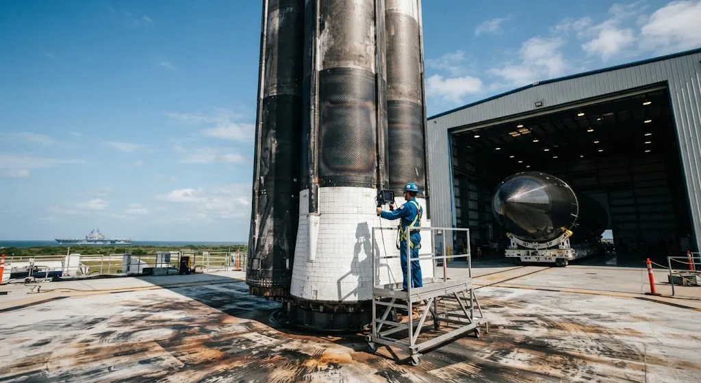
The commercial space industry has undergone a fundamental shift with the advent of reusable launch vehicles (RLVs). Companies like SpaceX, Rocket Lab, and Blue Origin have demonstrated that rockets can be recovered, refurbished, and reflown — reducing launch costs by 30-70% compared to expendable ar
Introduction
The commercial space industry has undergone a fundamental shift with the advent of reusable launch vehicles (RLVs). Companies like SpaceX, Rocket Lab, and Blue Origin have demonstrated that rockets can be recovered, refurbished, and reflown — reducing launch costs by 30-70% compared to expendable architectures. Carbon fiber reinforced polymer (CFRP) composites play a critical role in this transition, offering the high specific strength, stiffness, and thermal stability that reusable structures demand across multiple flight cycles.
Unlike expendable rockets, where structural components experience a single flight before disposal, reusable launch vehicle structures must survive repeated cycles of cryogenic propellant loading,Max-Q aerodynamic loading, engine vibration, atmospheric re-entry heating, and propulsive landing deceleration. This article explains how carbon fiber composites are engineered for reusable rocket structures, reviews the thermal protection systems that shield composite structures during re-entry, and examines the structural integrity and inspection requirements that enable safe multi-flight operations.
Carbon Fiber in Reusable Rocket Structures
Carbon fiber composites are used in several structural subsystems of reusable launch vehicles, each with distinct performance requirements:
- Interstage structures: The cylindrical or conical section connecting the first and second stages is a primary candidate for CFRP construction. The interstage must withstand axial compression during ascent, bending loads during separation, and thermal cycling between cryogenic propellant temperatures and ambient conditions. Carbon fiber interstages achieve 40-50% weight savings over aluminum equivalents, directly translating to payload capacity gains.
- Fairings: Payload fairings protect satellites during ascent and must separate cleanly at altitude. Reusable fairings — pioneered by SpaceX with its payload fairing recovery program — are large CFRP shell structures (5-7 meters diameter) that survive ocean splashdown or mid-air capture. The fairing must resist acoustic loads of 140 dB during ascent, aerodynamic heating to 300-500 degrees C during re-entry, and impact loads during recovery.
- Engine sections and thrust structures: The thrust structure transmits engine loads to the vehicle frame while accommodating thermal expansion differentials between hot engine components and ambient-temperature structures. CFRP thrust structures with thermal isolation layers reduce heat transfer to composite elements below their degradation threshold.
- Landing legs and grid fins: Reusable first-stage boosters require deployable landing legs and aerodynamic control surfaces (grid fins) that withstand repeated deployment, aerodynamic loads, and landing impact. Carbon fiber grid fins — used on Falcon 9 — provide the stiffness-to-weight ratio needed for precise aerodynamic steering during descent.
Thermal Protection Challenges for Reusable Composites
Reusable launch vehicle structures face thermal environments that differ fundamentally from expendable rockets. The key thermal challenge is not peak temperature — which is managed by dedicated thermal protection systems (TPS) — but rather thermal cycling fatigue, where repeated heating and cooling cycles degrade composite properties over time.
| Flight Phase | Peak Temperature at Structure | Duration | Primary Thermal Challenge |
|---|---|---|---|
| Ascent (through atmosphere) | 150-250 degrees C (aerodynamic heating) | 60-120 seconds | Ablative surface heating, acoustic-thermal coupling |
| Orbital coast | -150 to +120 degrees C (sun/shade cycling) | Hours to days | Thermal cycling fatigue, propellant tank cryogenic stress |
| Re-entry | 300-800 degrees C (without TPS protection) | 300-600 seconds | Radiative and convective heating, plasma interaction |
| Propulsive landing | 200-400 degrees C (engine plume impingement) | 10-30 seconds | Localized convective heating, thermal shock |
After 10-20 flight cycles, thermal fatigue can reduce interlaminar shear strength by 10-25% and compressive strength by 5-15% in carbon fiber composites, depending on the resin system and peak temperature exposure. This property degradation must be accounted for in structural design margins and inspection intervals.
Thermal Protection Systems for Composite Structures
Reusable thermal protection systems for composite rocket structures use several approaches, each suited to different temperature ranges and reusability requirements:
- Reusable surface insulation (RSI): Ceramic tile systems — similar to those used on the Space Shuttle — protect composite structures from convective heating during re-entry. RSI tiles are bonded to the composite surface with strain-isolating pads that accommodate thermal expansion mismatch. The tiles are inspected and repaired between flights.
- Flexible reusable surface insulation (FRSI): Felt-like ceramic blankets that wrap around composite structures, providing thermal protection up to 1,200 degrees C. FRSI is lighter than rigid RSI tiles and easier to inspect, making it suitable for large-area protection of fairings and interstages.
- PICA (Phenolic Impregnated Carbon Ablator): A lightweight ablative material used for re-entry capsule heat shields and high-heat-flux regions. PICA-X, the reusable variant, can withstand 10+ re-entry cycles with minimal erosion, protecting composite structures underneath from peak temperatures exceeding 2,000 degrees C.
- Transpiration cooling: An active thermal protection method where coolant fluid is forced through porous composite walls, absorbing heat through phase change or convective cooling. This approach is under development for next-generation reusable vehicles where passive TPS weight penalties are unacceptable.
Structural Integrity Across Multiple Flights
The structural integrity of reusable carbon fiber launch vehicle components is governed by three degradation mechanisms that do not affect expendable structures:
- Thermal cycling fatigue: Repeated heating and cooling cycles create cyclic thermal stresses at the fiber-matrix interface due to the mismatch in coefficients of thermal expansion (CTE) between carbon fibers (near-zero axial CTE) and epoxy resin (30-50 x 10^-6 /degrees C). Over 10-20 cycles, micro-cracks accumulate in the matrix, reducing interlaminar properties and increasing permeability.
- Vibration-induced fatigue: Engine combustion instabilities and aerodynamic buffet loads create high-cycle fatigue conditions that propagate matrix micro-cracks into fiber-level damage. Reusable structures must demonstrate fatigue life exceeding the planned mission count by a factor of 3-5.
- Moisture and propellant exposure: Repeated cycles of cryogenic propellant loading and ambient recovery create condensation and moisture ingress in composite micro-voids. Moisture absorption reduces the glass transition temperature of the resin matrix, lowering the allowable operating temperature for subsequent flights.
Inspection and Maintenance for Reusability
Reusable launch vehicle structures require inspection protocols that go beyond single-flight qualification:
- Post-flight visual inspection: Every returned stage undergoes visual inspection for surface damage, delamination, thermal discoloration, and impact marks. Automated visual inspection using structured-light scanning can detect surface anomalies down to 0.5 mm depth resolution.
- Ultrasonic inspection: Phased-array ultrasonic testing (PAUT) scans detect subsurface delamination, void growth, and fiber breakage that are not visible on the surface. PAUT inspection of a Falcon 9-class booster takes approximately 8-12 hours.
- Thermographic inspection: Flash thermography or lock-in thermography maps near-surface thermal diffusivity variations, identifying regions of moisture ingress, micro-cracking, or adhesive degradation in bonded joints.
- Destructive coupon testing: Representative coupon specimens bonded to the structure during manufacturing are removed and tested at intervals (e.g., every 5 flights) to track property degradation trends and validate remaining useful life predictions.
Frequently Asked Questions
How many flights can a carbon fiber reusable rocket structure sustain before replacement?
Current-generation reusable carbon fiber structures are designed for 10-20 flight cycles with periodic inspection and minor repairs. SpaceX has reflown Falcon 9 first-stage boosters over 20 times with structural refurbishment between flights. The limiting factor is typically thermal protection system wear rather than composite structural degradation — the composite itself can often sustain more cycles than the TPS tiles bonded to it. Next-generation vehicles target 100+ flights through improved resin systems, enhanced thermal protection, and predictive maintenance algorithms.
What are the weight penalties of reusable thermal protection systems on composite structures?
Thermal protection systems add 15-30% to the dry weight of the protected composite structure. A reusable RSI tile system adds approximately 2-5 kg/m2, while FRSI blankets add 1-3 kg/m2. For a Falcon 9-class booster with 200 m2 of TPS coverage, this translates to 400-1,000 kg of thermal protection mass. The weight penalty is offset by the cost savings from reusability — refurbishment costs of $10-15M per booster versus $60M for a new booster.
How does carbon fiber compare to aluminum-lithium alloy for reusable rocket structures?
Carbon fiber composites offer 20-30% weight savings over aluminum-lithium alloys for equivalent structural stiffness, which is critical for maximizing payload capacity. However, aluminum-lithium is easier to inspect (no hidden delamination modes), simpler to repair (welding or riveting), and more predictable in its fatigue behavior. Several RLV programs use hybrid approaches — CFRP for weight-critical structures (fairings, interstages) and aluminum-lithium for inspection-critical structures (thrust structures, tank walls).
Conclusion
Carbon fiber composites are enabling the reusable launch vehicle revolution by providing the specific strength, stiffness, and thermal stability that multi-flight structures demand. The thermal protection systems that shield composite structures during re-entry, the structural integrity analysis that accounts for thermal cycling fatigue, and the inspection protocols that verify continued airworthiness across multiple flights are all essential elements of a successful reusable architecture. As the commercial space industry targets higher flight rates and lower costs, the demand for optimized carbon fiber reusable launch vehicle structures will continue to grow.
For engineers developing reusable launch vehicle programs, the selection of carbon fiber materials, thermal protection systems, and inspection protocols must be integrated from the design phase. Explore our carbon fiber fabrics and aerospace-grade materials, or contact our engineering team to discuss material qualification and thermal protection solutions for your reusable launch vehicle program.
Part of topic
Related Articles
- Carbon Fiber Underwater Robots and AUVs: Hydrostatic Pressure and Corrosion Resistance
- Carbon Fiber Electric Aircraft Propulsion: Lightweight Motor Housings and Nacelle Structures
- Carbon Fiber Mooring for Floating Offshore Wind: Fatigue and Corrosion in Deep Water
- Carbon Fiber Bicycle Frame Optimization: Layup Design and Manufacturing for Competitive Racing
- Carbon Fiber CFRP Retrofit for Infrastructure: Bridge and Building Seismic Strengthening
- Carbon Fiber Medical Imaging Equipment: Lightweight Gantry and Couch Structures for MRI/CT
Interested in Our Products?
Contact our team for competitive pricing and technical specifications.
Get a QuoteRelated Products

Carbon Fiber Plate — 3K Twill T700 1.5mm
Thin 1.5mm carbon fiber plate with 3K twill weave surface. Lightweight and stiff, commonly used for covers, panels, drone bodies, and applications requiring a premium aesthetic appearance.

Carbon Fiber Plate — 3K Twill T700 3.0mm
Medium-thickness 3.0mm carbon fiber plate offering significantly higher load capacity while maintaining attractive 3K twill finish. Suitable for structural brackets, reinforcement plates, and load-bearing panels.

Square Carbon Fiber Tube — 3K Twill T700
Square cross-section carbon fiber tube manufactured with 3K twill weave for torsional strength. Preferred for structural frames, trusses, and support columns where rectangular geometry offers design flexibility.

Carbon Fiber Plate — UD Unidirectional T700
Unidirectional carbon fiber plate with all fibers oriented in a single direction for maximum strength along the fiber axis. Essential for structural reinforcements, splints, and applications where load direction is predictable.

Round Carbon Fiber Tube — UD Unidirectional T700
Unidirectional (UD) round tube with all fibers aligned axially for maximum longitudinal stiffness. Ideal for applications requiring high bending rigidity with minimal weight, such as shafts, struts, and structural reinforcements.