
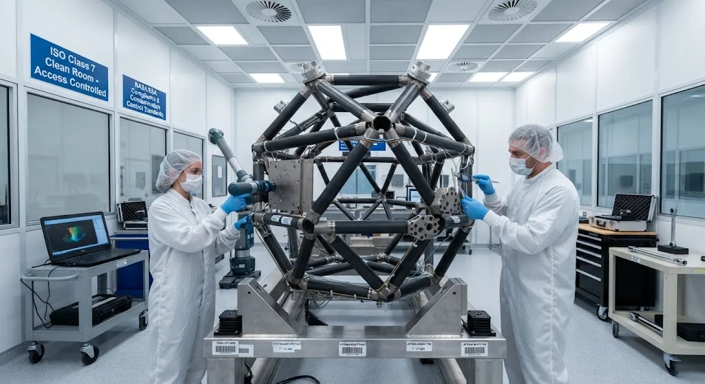
Carbon fiber composite truss structures provide the dimensional stability and low mass required for satellite platforms operating in extreme thermal environments. This article covers material selection, design approaches, and on-orbit performance of CFRP satellite trusses.
Introduction
Satellite structures must survive the extreme environment of space while maintaining precise dimensional alignment of optical instruments, antennas, and payload interfaces. Carbon fiber reinforced polymer (CFRP) truss structures have become the standard for satellite platforms, offering an unmatched combination of low mass, high stiffness, and exceptional dimensional stability across wide temperature ranges.
The unique demands of satellite structures — launch loads, on-orbit thermal cycling between sunlit and shadowed conditions, and the need for extreme precision over mission lifetimes of 15+ years — make material selection and structural design critical. CFRP truss structures address these requirements through optimized fiber orientation, resin system selection, and structural configuration.
Thermal Dimensional Stability
The most critical property for satellite truss structures is dimensional stability under thermal cycling:
Coefficient of thermal expansion (CTE): CFRP can be engineered to achieve near-zero CTE through appropriate fiber orientation. Quasi-isotropic laminates typically show CTE of 0–2 × 10⁻⁶/°C, compared to 23 × 10⁻⁶/°C for aluminum. This near-zero CTE ensures that antenna reflectors, optical benches, and instrument mounting structures maintain their geometry through temperature swings of ±150°C.
Thermal conductivity: While CFRP has lower thermal conductivity than metals, this can be managed through thermal design — heat pipes, thermal blankets, and heater systems — to maintain acceptable temperature gradients across the structure.
Microcracking resistance: Repeated thermal cycling can cause matrix microcracking in CFRP, degrading stiffness and dimensional stability. Resin selection and ply orientation design minimize microcracking risk while maintaining required properties.
Material Systems
Satellite truss structures use specialized CFRP material systems:
Fiber selection: High modulus carbon fibers (M40J, M55J, M60J) are preferred for satellite structures due to their superior stiffness and thermal dimensional stability. Ultra-high modulus fibers (pitch-based, K13D2U) provide even lower CTE but reduced strain capability.
Resin systems: Space-qualified epoxy resins offer the best combination of properties, outgassing performance, and processing characteristics. Cyanate ester resins provide lower moisture absorption and improved dimensional stability. Both must meet NASA or ESA outgassing specifications (ASTM E595).
Adhesive systems: Structural adhesives for truss joint bonding must maintain strength and stiffness across the full temperature range while resisting microcracking. Toughened epoxy adhesives with controlled glass transition temperature (Tg) are typically specified.
Structural Design
Satellite truss structures employ several design approaches:
Tubular trusses: Circular or triangular tube members connected at nodes provide high stiffness-to-weight ratios. Tubes are typically manufactured by filament winding or roll-wrapping, with bonded or mechanically fastened node connections.
Honeycomb sandwich panels: CFRP face sheets bonded to aluminum or Nomex honeycomb cores provide high bending stiffness at low mass. Used for equipment panels, optical bench structures, and antenna reflectors.
Integrated structures: Advanced designs integrate multiple functions — structural support, thermal management, radiation shielding — into single CFRP components, reducing part count and mass.
Manufacturing Considerations
Satellite CFRP structures require specialized manufacturing processes:
Clean room manufacturing: Assembly in ISO Class 7 or better clean rooms prevents contamination that could affect optical performance or outgassing behavior.
Autoclave processing: Most satellite CFRP structures are autoclave-cured at 120–180°C under 3–7 bar pressure to achieve low void content (< 1%) and consistent fiber volume fraction.
Dimensional verification: Coordinate measuring machine (CMM) inspection and laser tracking verify dimensional accuracy against tight tolerances — often ±0.1 mm over meter-scale structures.
Thermal cycling: Some specifications require thermal cycling of flight hardware to relieve residual stresses and verify dimensional stability before flight acceptance.
On-Orbit Performance
CFRP satellite truss structures have demonstrated excellent on-orbit performance:
Dimensional stability: Multiple satellite missions have confirmed that well-designed CFRP structures maintain their ground-measured dimensions within microradians over multi-year missions, even through hundreds of thermal cycles.
Survival: CFRP structures have survived launch loads exceeding 15 g RMS and acoustic environments up to 143 dB without damage, validating the structural design and manufacturing quality.
Aging: Long-term on-orbit data shows minimal property degradation for properly designed and manufactured CFRP structures, supporting mission lifetimes of 15–20 years.
Conclusion
Carbon fiber composite truss structures provide the essential combination of low mass, high stiffness, and thermal dimensional stability required for satellite platforms. As satellite designs push toward larger structures, higher precision instruments, and longer mission lifetimes, CFRP truss technology will continue to advance, enabling the next generation of communications, Earth observation, and scientific spacecraft.
Part of topic
Related Articles
- Carbon Fiber Mooring for Floating Offshore Wind: Fatigue and Corrosion in Deep Water
- Carbon Fiber Bicycle Frame Optimization: Layup Design and Manufacturing for Competitive Racing
- Carbon Fiber CFRP Retrofit for Infrastructure: Bridge and Building Seismic Strengthening
- Carbon Fiber Medical Imaging Equipment: Lightweight Gantry and Couch Structures for MRI/CT
- Carbon Fiber EV Battery Enclosures: Crash Safety and Electromagnetic Shielding Design
- Carbon Fiber Structures for Low-Altitude Economy: UAV Airframes and eVTOL Components
Interested in Our Products?
Contact our team for competitive pricing and technical specifications.
Get a QuoteRelated Products

Carbon Fiber Plate — 3K Twill T700 3.0mm
Medium-thickness 3.0mm carbon fiber plate offering significantly higher load capacity while maintaining attractive 3K twill finish. Suitable for structural brackets, reinforcement plates, and load-bearing panels.

Carbon Fiber Plate — 3K Twill T700 1.5mm
Thin 1.5mm carbon fiber plate with 3K twill weave surface. Lightweight and stiff, commonly used for covers, panels, drone bodies, and applications requiring a premium aesthetic appearance.

Square Carbon Fiber Tube — 3K Twill T700
Square cross-section carbon fiber tube manufactured with 3K twill weave for torsional strength. Preferred for structural frames, trusses, and support columns where rectangular geometry offers design flexibility.

Carbon Fiber Plate — UD Unidirectional T700
Unidirectional carbon fiber plate with all fibers oriented in a single direction for maximum strength along the fiber axis. Essential for structural reinforcements, splints, and applications where load direction is predictable.

Round Carbon Fiber Tube — UD Unidirectional T700
Unidirectional (UD) round tube with all fibers aligned axially for maximum longitudinal stiffness. Ideal for applications requiring high bending rigidity with minimal weight, such as shafts, struts, and structural reinforcements.