
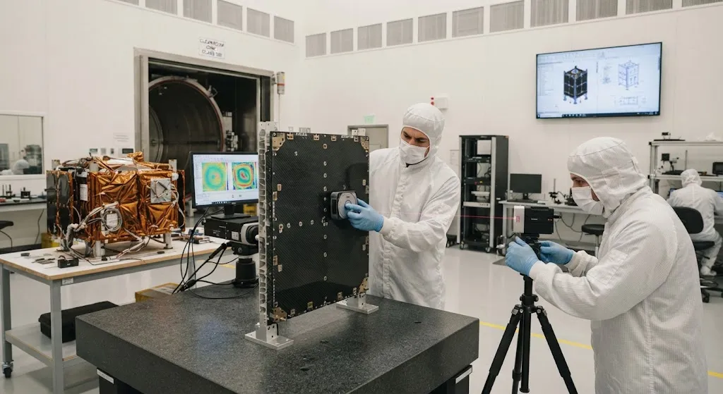
An optical satellite payload is only as good as the structure that holds its mirrors, lenses, and focal-plane electronics stable. In low Earth orbit, that structure must survive temperature swings of more than two hundred degrees Celsius across a ninety-minute orbit — from full sun to f
Introduction
An optical satellite payload is only as good as the structure that holds its mirrors, lenses, and focal-plane electronics stable. In low Earth orbit, that structure must survive temperature swings of more than two hundred degrees Celsius across a ninety-minute orbit — from full sun to full eclipse, hundreds of times per day — while keeping an optical path that can be tens of centimeters to several meters long dimensionally faithful to a few micrometers. Aluminum, the traditional structural metal, expands by about 23 parts per million per degree Celsius, which across a one-meter optical bench and a twenty-degree structural gradient produces thermal distortion measured in hundreds of micrometers. That is two orders of magnitude too much for a high-resolution imaging or laser-communication payload. Carbon fiber composites solve this problem because their coefficient of thermal expansion can be designed down to essentially zero, or even slightly negative, along critical axes.
This article is written for satellite program managers, structural engineers, and procurement specialists who must specify, verify, and source carbon fiber composite structures for optical payloads in low Earth orbit. We will cover why thermal stability matters, how carbon fiber achieves near-zero expansion, the laminate design rules that make it work, and the verification steps that separate genuine space-grade material from aerospace-adjacent product.
Why Thermal Stability Drives Satellite Structure Design
The thermal environment of low Earth orbit is the harshest, most rapidly cycling environment any precision structure faces. A satellite in a sun-synchronous orbit transitions from direct solar illumination to full Earth shadow once per orbit, so every eighty to one hundred minutes the structure experiences a thermal soak change of 150-200 °C. For an optical payload, the consequences are unforgiving:
- Focus and alignment drift: any expansion of the optical bench changes the distance between primary mirror and focal plane, which directly defocuses the image. A 300 K reference temperature swing is not unusual over a mission; even a few micrometers of drift degrade resolution.
- Differential thermal distortion: a structure that expands asymmetrically bows and twists, misaligning mirrors relative to the instrument axis and corrupting pointing accuracy during the very observation windows when stability matters most.
- Thermal-elastic stresses: if bonded joints and interfaces see large relative displacement, the induced stresses can microcrack facesheets or loosen bonded inserts over thousands of cycles, degrading the structure slowly and unpredictably.
The engineering answer has historically been one of two routes: actively control temperature with heaters and multi-layer insulation to shrink gradients, or choose a material whose expansion is so low that passive stability suffices. Carbon fiber composite is the second route, and it is the reason optical payload benches, instrument structures, and high-stability panels in modern LEO satellites are dominated by CFRP honeycomb sandwich and CFRP lattice structures.
Carbon Fiber's Near-Zero Expansion Advantage
The expansion behavior of carbon fiber composites is fundamentally different from that of metals because it is directional. A unidirectional carbon laminate expands essentially along two orthogonal axes: parallel to the fibers, where the carbon fiber dominates and expansion is tiny or negative, and perpendicular to the fibers, where the resin dominates and expansion is positive and relatively large.
| Material | Axial CTE (µm/m/°C) | Specific stiffness | Typical satellite use |
|---|---|---|---|
| Aluminum 6061-T6 | +23 | Baseline | Legacy structures, brackets |
| Standard-modulus CFRP (T300-class) | -0.4 to +0.2 | ~4-5 times aluminum | Panels, secondary structure |
| High-modulus CFRP (M55J/M60J-class) | -1.1 to -0.9 (fiber-dominated) | ~6-8 times aluminum | Optical benches, precision structures |
| Titanium Ti-6Al-4V | +8.6 | ~1.5 times aluminum stiffness/density | Fittings, inserts, interfaces |
The axial expansion numbers above are fiber-direction values; a real laminate combines plies at multiple angles so the net in-plane expansion is a weighted average. The key insight is that by selecting the angle mix, a laminate designer can tune the in-plane CTE to essentially zero. High-modulus fiber such as the M55J or M60J class is preferred for this because its fiber-direction expansion is already about -1 ppm/°C, giving the designer more room to balance positive resin-dominated contributions.
Laminate Design Rules for Dimensional Stability
Designing a thermally stable CFRP structure is an exercise in balancing contributions, and four rules dominate practice:
- Use high-modulus fiber for the critical laminae: M-class fiber (modulus 377-588 GPa) contributes strong negative axial expansion and drives up laminate stiffness, so thinner panels achieve the same stability with less mass. Standard-modulus fiber works for general panels but leaves less CTE design margin.
- Tune ply angles for zero net in-plane CTE: a quasi-isotropic layup gives near-zero expansion in all in-plane directions but slightly positive values; switching a share of plies to 0° increases the negative axial contribution. The designer iterates the angle mix so the expanded properties — stiffness, strength, and CTE — all meet requirements simultaneously, because optimizing CTE alone usually sacrifices another property.
- Control moisture effects: cured epoxy absorbs moisture from the air, and desorption in vacuum causes shrinkage that mimics thermal contraction. Space structures are protected with moisture-barrier films or designed so that the moisture-shrinkage direction opposes expected thermal shift, and verification includes vacuum conditioning before metrology.
- Manage microcracking: thermal cycling creates microcracks in laminates at ply interfaces, and microcracking relaxes the laminate, causing a permanent CTE shift and dimension change after the first few hundred cycles. Low-elongation high-modulus fiber laminates are more prone to this, so crack-resistant matrix systems and cycling verification before final machining are standard practice.
Structural Forms in LEO Satellites
The material advantage translates into a small family of structural forms that dominate modern optical satellite design:
- Honeycomb sandwich panels: CFRP facesheets bonded to aluminum or CFRP honeycomb core. The panel CTE is dominated by the carbon facesheets while the core carries shear and keeps the panel light and stiff. Used for instrument decks, solar-array substrates, and high-stability platforms.
- Optical benches and metering structures: near-zero-CTE CFRP panels or tubes that hold the optical chain. High-modulus carbon produces benches whose length change across a mission thermal envelope is on the order of a few micrometers over meters of path.
- CFRP tubular frames: for open lattice metering structures where mirrors must stay fixed relative to each other with gaps between them. Tube CTE is designed negative so that a structure warming slightly contracts, compensating any residual positive expansion in the metal end fittings.
- Hybrid metal-composite joints: invar or titanium inserts bonded into CFRP panels to carry fastener loads. Invar (CTE about 1-2 ppm/°C) and titanium are chosen to minimize joint mismatch with the near-zero expansion composite.
Verification: What Separates Space-Grade from the Rest
Not every CFRP panel sold for "aerospace" use is suitable for an optical LEO payload. The verification program that separates space-grade material has five pillars:
| Verification step | Method | Why it matters |
|---|---|---|
| CTE measurement | Interferometry or dilatometry over the mission temperature range | Confirms the designed near-zero expansion actually holds across -100 to +80 °C |
| Thermal cycling | Several hundred cycles representative of mission life | Reveals microcrack-driven CTE drift before the structure flies |
| Vacuum conditioning and mass loss | Vacuum bakeout, ASTM E595 for outgassing | Prevents molecular contamination of optical surfaces; avoids moisture-shrink surprises |
| Mechanical verification | Stiffness, strength, and modal testing on flight-representative panels | Bridges the gap between coupon data and the as-built structure |
| Lot and material traceability | Certified fiber and resin batches, documented cure cycles | Locks the performance to a repeatable process, not a one-off build |
For procurement teams, the practical consequence is that the supplier's process documentation matters as much as the test results. A space-grade CFRP panel is the product of a controlled process — certified fiber, qualified prepreg, documented autoclave cycle, and metrology on the exact article that will fly. Suppliers who cannot show that chain are offering aerospace-adjacent product at aerospace prices.
Cost and Lead-Time Realities
Space-grade CFRP is expensive, and the cost structure is worth understanding before budgeting. High-modulus M-class fiber costs several times standard-modulus fiber per kilogram. Certified, traceable prepreg with documented lot data adds another premium. Autoclave-qualified lamination, vacuum conditioning, and interferometric CTE verification are slow, specialized operations that dominate the manufacturing cost of a precision optical bench. Lead times therefore run long — often six to twelve months for a qualified optical bench structure from scratch, less if the laminate system and process are already qualified for your application. Budgeting should reflect that stability, not strength, is the expensive requirement: a structure sized for load bearing alone is far cheaper than one sized for micrometer-level thermal stability.
Frequently Asked Questions
Why is aluminum not good enough for optical satellite payload structures?
Because aluminum expands by about 23 µm per meter per degree Celsius. A one-meter optical bench experiencing a 20 °C structural gradient distorts by roughly 460 µm — far beyond the micrometer-level stability a high-resolution optical payload needs. Aluminum's specific stiffness is also about 4-8 times lower than carbon composites, so the structure is both heavier and less dimensionally stable. Aluminum remains useful for brackets and the main bus where its cost, machining ease, and well-understood behavior matter more than stability.
Can a CFRP optical bench really hold micrometer stability across a mission?
Yes, when properly designed. By mixing high-modulus fiber plies so the in-plane CTE lands near zero, a bench's length change across the mission temperature envelope is on the order of a few micrometers over several meters of optical path. The caveat is that this only holds if the laminate is designed, cycled, and verified as a system: moisture effects controlled, microcrack relaxation characterized, and CTE measured by interferometry across the full temperature range. Certification data, not datasheet averages, is what makes the claim credible.
What should I verify before accepting a space-grade CFRP structure from a supplier?
Ask for five things: interferometric CTE data measured over the mission temperature range on an actual article, not a coupon average; thermal cycling results showing no significant CTE drift after hundreds of cycles; vacuum outgassing data per ASTM E595; mechanical test results linking coupon allowables to the as-built panel; and full traceability from certified fiber and resin batches through the documented cure cycle. If any of the five is missing, the structure has not been qualified for optical LEO service regardless of what its brochure claims.
Conclusion
Carbon fiber composite structures have become the standard for optical payload platforms in low Earth orbit because they solve the one problem metals cannot: dimensional stability across a brutal thermal environment. By using high-modulus fiber and tuning laminate angles, designers achieve near-zero coefficient of thermal expansion along critical axes, turning a 150-200 °C per-orbit temperature swing into a structural displacement of only a few micrometers. The trade-off is cost, lead time, and verification rigor — but for a payload whose entire value is image quality or laser-link stability, that trade-off is exactly where money should be spent.
If you are sourcing high-modulus carbon fiber or qualified composite structures for space applications, review our carbon fiber product range or contact our engineering team to discuss M-class fiber selection, laminate design for near-zero CTE, and the verification documentation your optical payload program requires.
Part of topic
Related Articles
- Carbon Fiber Mooring for Floating Offshore Wind: Fatigue and Corrosion in Deep Water
- Carbon Fiber Bicycle Frame Optimization: Layup Design and Manufacturing for Competitive Racing
- Carbon Fiber CFRP Retrofit for Infrastructure: Bridge and Building Seismic Strengthening
- Carbon Fiber Medical Imaging Equipment: Lightweight Gantry and Couch Structures for MRI/CT
- Carbon Fiber EV Battery Enclosures: Crash Safety and Electromagnetic Shielding Design
- Carbon Fiber Structures for Low-Altitude Economy: UAV Airframes and eVTOL Components
Interested in Our Products?
Contact our team for competitive pricing and technical specifications.
Get a QuoteRelated Products

Carbon Fiber Plate — 3K Twill T700 3.0mm
Medium-thickness 3.0mm carbon fiber plate offering significantly higher load capacity while maintaining attractive 3K twill finish. Suitable for structural brackets, reinforcement plates, and load-bearing panels.

Carbon Fiber Plate — 3K Twill T700 1.5mm
Thin 1.5mm carbon fiber plate with 3K twill weave surface. Lightweight and stiff, commonly used for covers, panels, drone bodies, and applications requiring a premium aesthetic appearance.

Square Carbon Fiber Tube — 3K Twill T700
Square cross-section carbon fiber tube manufactured with 3K twill weave for torsional strength. Preferred for structural frames, trusses, and support columns where rectangular geometry offers design flexibility.

Carbon Fiber Plate — UD Unidirectional T700
Unidirectional carbon fiber plate with all fibers oriented in a single direction for maximum strength along the fiber axis. Essential for structural reinforcements, splints, and applications where load direction is predictable.

Round Carbon Fiber Tube — UD Unidirectional T700
Unidirectional (UD) round tube with all fibers aligned axially for maximum longitudinal stiffness. Ideal for applications requiring high bending rigidity with minimal weight, such as shafts, struts, and structural reinforcements.