
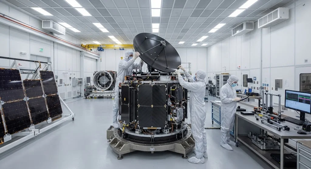
Carbon fiber satellite structures represent one of the most demanding applications for advanced composite materials, where dimensional stability through years of thermal cycling in low Earth orbit (LEO) or geostationary orbit (GEO) is non-negotiable. Satellite components such as optical
Introduction
Carbon fiber satellite structures represent one of the most demanding applications for advanced composite materials, where dimensional stability through years of thermal cycling in low Earth orbit (LEO) or geostationary orbit (GEO) is non-negotiable. Satellite components such as optical benches, antenna reflectors, solar array panels, and bus structures must maintain micrometer-level dimensional precision while experiencing temperature swings of -150°C to +150°C during each orbit. Carbon fiber composites have become the material of choice for these applications because they offer the unique combination of ultra-low coefficient of thermal expansion (CTE), high specific stiffness, and radiation resistance that no metallic material can match.
For B2B buyers in the space industry, selecting the right carbon fiber satellite structure material requires understanding the interplay between fiber type, matrix system, layup configuration, and environmental degradation mechanisms. This article provides a technical framework for evaluating carbon fiber composites for satellite applications, with specific data on CTE values, mechanical property retention after radiation exposure, and outgassing requirements that drive material qualification.
Why Carbon Fiber Is Essential for Satellite Structures
The space environment imposes unique material requirements that make carbon fiber composites almost exclusively suitable for precision satellite structures. The fundamental advantages are summarized below:
- Ultra-low CTE: Carbon fiber laminates can be designed with near-zero or even negative CTE in one or more directions, matching the CTE requirements of optical systems and RF antennas that must maintain alignment through thermal cycling.
- High specific stiffness: Carbon fiber composites deliver 3-5 times the specific stiffness of aluminum alloys, reducing launch mass while maintaining structural rigidity for antenna pointing and optical alignment.
- Radiation resistance: Carbon fiber composites maintain mechanical properties after prolonged exposure to the ionizing radiation environment in LEO and GEO, unlike many polymers that degrade rapidly.
- Vacuum stability: Properly qualified carbon fiber composites exhibit minimal outgassing in the vacuum of space, preventing contamination of sensitive optical and electronic surfaces.
- Dimensional stability over time: Carbon fiber structures exhibit minimal creep and stress relaxation, maintaining dimensional precision over 15-20 year satellite lifetimes.
These properties make carbon fiber the dominant material for satellite structures across all orbit classes, from CubeSat optical benches to GEO communication satellite bus structures exceeding 20 meters in dimension.
Material Selection for Carbon Fiber Satellite Structures
The choice of carbon fiber type and matrix system for satellite structures is driven by CTE requirements, mechanical property needs, and environmental resistance. The following table compares the most common carbon fiber grades used in space applications:
| Property | Standard Modulus (T300-class) | Intermediate Modulus (T800-class) | High Modulus (M60J-class) | Ultra-High Modulus (M70J-class) |
|---|---|---|---|---|
| Tensile modulus | 230 GPa | 294 GPa | 588 GPa | 690 GPa |
| Tensile strength | 3,530 MPa | 5,490 MPa | 3,620 MPa | 3,430 MPa |
| Typical laminate CTE | -0.5 to +1.0 ppm/°C | -0.8 to +0.5 ppm/°C | -1.2 to -0.3 ppm/°C | -1.5 to -0.5 ppm/°C |
| Radiation tolerance | Excellent | Excellent | Good | Moderate |
| Relative cost | 1.0x | 1.5x | 3-5x | 5-8x |
| Primary satellite use | Bus structures, panels | Primary structures, reflectors | Optical benches, antenna | Precision optics, subsystems |
For most satellite bus structures, standard modulus or intermediate modulus fibers provide the optimal balance of CTE control, mechanical properties, and cost. High modulus and ultra-high modulus fibers are reserved for applications demanding the lowest possible CTE, such as optical instrument benches where nanometer-level dimensional stability is required.
CTE Matching Strategies for Satellite Structures
The primary design challenge for carbon fiber satellite structures is achieving the target CTE in the correct directions while maintaining sufficient mechanical properties. Several strategies are employed:
- Quasi-isotropic layup: [0/±45/90]s layups produce near-zero CTE in all in-plane directions (typically -0.5 to +0.5 ppm/°C), suitable for general bus structures and panels where multi-directional thermal stability is required.
- Near-zero unidirectional CTE: Specific ply orientations can achieve CTE values below 0.1 ppm/°C in one direction by balancing positive CTE from the matrix with negative CTE from the carbon fiber. This approach is used for antenna reflectors and optical mounts requiring precision alignment.
- Negative CTE design: Layups dominated by high-modulus fibers in the 0° direction can produce negative CTE (-1.0 to -2.0 ppm/°C), used for active thermal compensation structures that counteract positive CTE in attached metallic components.
- Hybrid metal-composite structures: Carbon fiber face sheets bonded to metallic honeycomb cores create sandwich panels with controlled CTE through core material selection (aluminum, Invar, or titanium). This approach provides both dimensional stability and damage tolerance.
The CTE of a carbon fiber laminate is not a fixed material property but a design variable that depends on fiber type, fiber volume fraction, layup orientation, cure temperature, and post-cure history. Accurate CTE prediction requires validated laminate analysis tools and coupon-level thermal expansion testing.
Space Environment Effects on Carbon Fiber Satellite Structures
Carbon fiber satellite structures must maintain performance through multiple space environment degradation mechanisms. The following table summarizes key environmental factors and their effects on carbon fiber composites:
| Environment Factor | LEO Exposure (15-year) | GEO Exposure (15-year) | Effect on Carbon Fiber Composite |
|---|---|---|---|
| Thermal cycling | ~86,000 cycles (-150°C to +150°C) | ~365 cycles (-170°C to +130°C) | Micromatrix cracking, CTE drift, stiffness reduction |
| Atomic oxygen | High flux, surface erosion | Negligible | Matrix surface recession, fiber exposure |
| UV radiation | Moderate, with eclipse periods | Continuous | Surface degradation, color change, minor property loss |
| Ionizing radiation | ~100 krad/year total dose | ~50 krad/year total dose | Matrix chain scission, minor modulus reduction |
| Vacuum outgassing | Continuous (< 1% TML, < 0.1% CVCM per ASTM E595) | Continuous | Contamination of optical/electronic surfaces if not qualified |
Atomic oxygen erosion is the most significant environmental challenge for LEO carbon fiber satellite structures, causing surface recession of the polymer matrix that can expose reinforcement fibers and degrade thermal control coatings. Protective coatings (SiO2, plasma-deposited ceramic layers) are routinely applied to LEO-facing surfaces. For GEO applications, UV and ionizing radiation effects on the matrix system are the primary degradation concerns, though carbon fiber composites generally maintain >85% of original mechanical properties after 15-year GEO exposure.
Structural Design Considerations for Carbon Fiber Satellite Components
Designing carbon fiber satellite structures requires balancing multiple performance requirements simultaneously. Key design considerations include:
- Laminate stacking sequence optimization: Ply orientations must be selected to achieve target CTE, maximize stiffness in load directions, and ensure balanced/symmetric layups to prevent thermal warping. Computational optimization tools are routinely used for complex structures.
- Joint design: Carbon fiber to metallic interface joints (for equipment mounting, solar array hinges, and antenna gimbals) must accommodate CTE mismatch between materials. Flexible adhesive bonds, kinematic mounts, and slotted holes are common solutions.
- Dimensional tolerance management: Post-cure dimensional changes and thermal history effects must be accounted for in tolerance budgets. Carbon fiber structures typically achieve ±50 μm dimensional accuracy on meter-scale components after thermal conditioning.
- Vibration and acoustic loads: Launch vibration and acoustic environments impose dynamic loads that require sufficient margin above static strength requirements. Carbon fiber composites' high specific stiffness and damping properties provide inherent advantages for vibration survival.
- Manufacturing process control: Autoclave-cured carbon fiber satellite structures require strict process control (temperature uniformity ±2°C, pressure stability ±5%) to achieve consistent CTE and mechanical properties across large structures.
These design considerations interact in complex ways, requiring iterative analysis and testing to optimize carbon fiber satellite structures for specific mission requirements.
Frequently Asked Questions
What CTE values can be achieved with carbon fiber satellite structures?
Carbon fiber satellite structures can achieve a wide range of CTE values depending on fiber type and layup design. Standard modulus quasi-isotropic laminates typically produce in-plane CTE of -0.5 to +0.5 ppm/°C. Near-zero unidirectional designs using intermediate modulus fibers can achieve CTE below 0.1 ppm/°C in the fiber direction. High modulus fibers can produce negative CTE values down to -2.0 ppm/°C for thermal compensation applications. The through-thickness CTE is typically 20-30 ppm/°C for all carbon fiber laminates, which must be accounted for in sandwich panel and bonded joint designs. Achieving a specific CTE target requires careful material selection, layup optimization, and coupon-level validation testing.
How do carbon fiber satellite structures survive launch vibration?
Carbon fiber satellite structures survive launch vibration through a combination of high specific stiffness, favorable damping properties, and conservative structural design margins. Typical launch qualification requires surviving random vibration levels of 10-15 g RMS across the frequency spectrum, plus sinusoidal vibration and shock loads from stage separation events. Carbon fiber composites' high stiffness-to-weight ratio means natural frequencies are pushed above the primary launch vehicle vibration spectrum, reducing dynamic amplification. Structural margins of 25-40% above limit loads are standard for flight hardware, and modal survey testing validates the analytical models used for stress and deflection predictions.
What are the outgassing requirements for carbon fiber satellite materials?
All materials used in carbon fiber satellite structures must meet NASA ASTM E595 outgassing requirements: Total Mass Loss (TML) less than 1.0% and Collected Volatile Condensable Material (CVCM) less than 0.1% when tested at 125°C for 24 hours in vacuum. Epoxy resin systems qualified for space use (such as Hexcel 8552, Cytec 5276-1) consistently meet these requirements with TML values of 0.3-0.8% and CVCM below 0.05%. Cyanate ester and bismaleimide (BMI) resin systems offer even lower outgassing for the most sensitive optical applications. Pre-qualification outgassing testing is mandatory for all matrix materials, and cured laminate outgassing is typically lower than neat resin values due to reduced volatile mobility in the crosslinked network.
Conclusion
Carbon fiber satellite structures provide the dimensional stability, radiation resistance, and specific stiffness that modern space missions demand. From standard modulus bus structures to ultra-high modulus optical benches, carbon fiber composites offer design flexibility that enables mission-critical performance across all orbit classes. The key to successful carbon fiber satellite structure design lies in understanding the interplay between material selection, layup configuration, and space environment effects, combined with rigorous process control during manufacturing.
For space industry buyers evaluating carbon fiber composites for satellite structures, the material selection and design process requires deep technical expertise and validated environmental data. Explore our space-qualified carbon fiber product range or contact our technical team to discuss material solutions for your satellite program requirements.
Part of topic
Related Articles
- Carbon Fiber Mooring for Floating Offshore Wind: Fatigue and Corrosion in Deep Water
- Carbon Fiber Bicycle Frame Optimization: Layup Design and Manufacturing for Competitive Racing
- Carbon Fiber CFRP Retrofit for Infrastructure: Bridge and Building Seismic Strengthening
- Carbon Fiber Medical Imaging Equipment: Lightweight Gantry and Couch Structures for MRI/CT
- Carbon Fiber EV Battery Enclosures: Crash Safety and Electromagnetic Shielding Design
- Carbon Fiber Structures for Low-Altitude Economy: UAV Airframes and eVTOL Components
Interested in Our Products?
Contact our team for competitive pricing and technical specifications.
Get a QuoteRelated Products

Carbon Fiber Plate — 3K Twill T700 1.5mm
Thin 1.5mm carbon fiber plate with 3K twill weave surface. Lightweight and stiff, commonly used for covers, panels, drone bodies, and applications requiring a premium aesthetic appearance.

Carbon Fiber Plate — 3K Twill T700 3.0mm
Medium-thickness 3.0mm carbon fiber plate offering significantly higher load capacity while maintaining attractive 3K twill finish. Suitable for structural brackets, reinforcement plates, and load-bearing panels.

Square Carbon Fiber Tube — 3K Twill T700
Square cross-section carbon fiber tube manufactured with 3K twill weave for torsional strength. Preferred for structural frames, trusses, and support columns where rectangular geometry offers design flexibility.

Carbon Fiber Plate — UD Unidirectional T700
Unidirectional carbon fiber plate with all fibers oriented in a single direction for maximum strength along the fiber axis. Essential for structural reinforcements, splints, and applications where load direction is predictable.

Round Carbon Fiber Tube — UD Unidirectional T700
Unidirectional (UD) round tube with all fibers aligned axially for maximum longitudinal stiffness. Ideal for applications requiring high bending rigidity with minimal weight, such as shafts, struts, and structural reinforcements.