
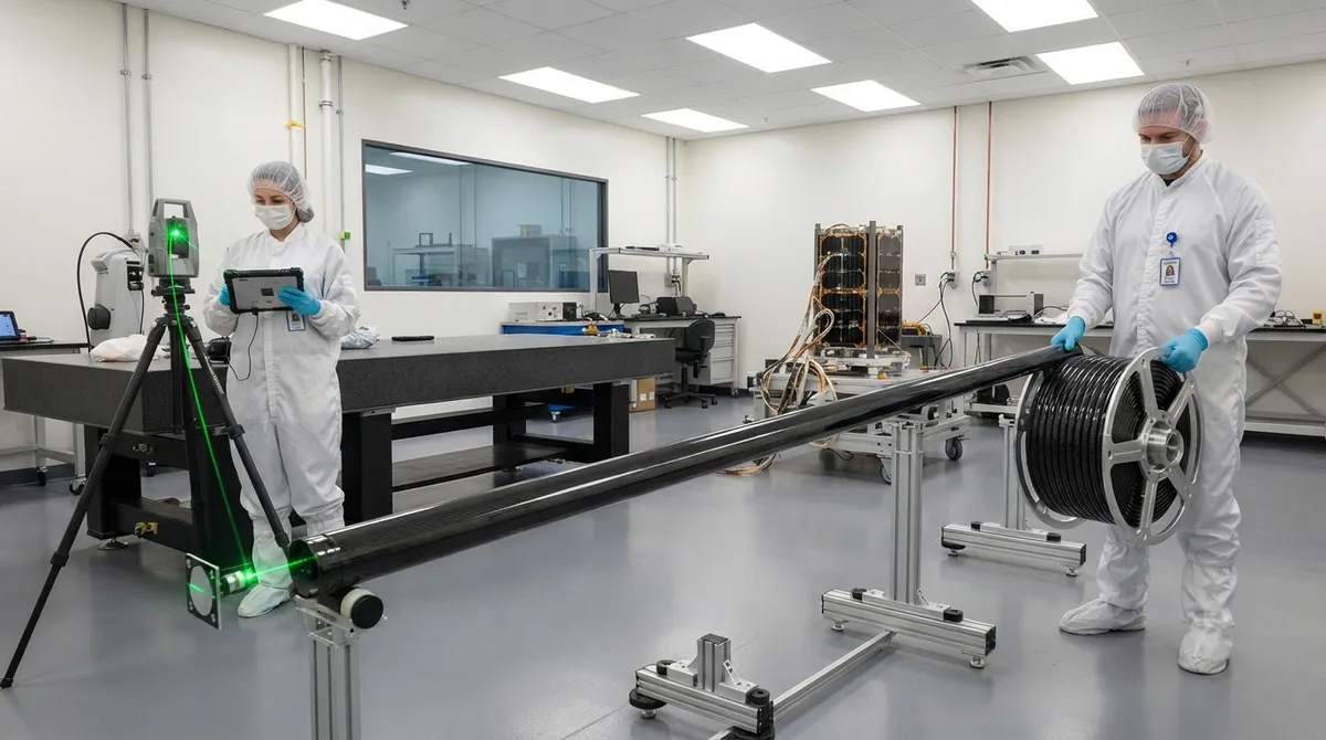
Carbon fiber deployable booms exist to solve both problems at once: they stow in a compact coil, then extend to lengths of several meters once the satellite reaches orbit, carrying instruments, solar sails, or antennas to a position far from the bus. Their defining material property — a
Introduction
Carbon fiber deployable booms exist to solve both problems at once: they stow in a compact coil, then extend to lengths of several meters once the satellite reaches orbit, carrying instruments, solar sails, or antennas to a position far from the bus. Their defining material property — a near-zero coefficient of thermal expansion — makes them uniquely suited to structures that must hold precise dimensional tolerances across the violent temperature swings of orbital day-night cycling.
The engineering challenge is demanding in execution: a boom must be thin enough to coil tightly, stiff enough to hold its deployed shape against thermal and dynamic loads, and stable enough to return to the same position every time it deploys. This article covers the thin-wall rollable boom family, thermal stability, stowed-volume trade-offs, and the qualification testing that determines whether a boom is fit for a mission.
Why Satellites Need Deployable Booms
A fixed structural arm sized for a 5-meter solar sail or a gravity-gradient stabilization system would dominate the spacecraft during launch, wasting mass and stowed volume. Deployable booms decouple the launch configuration from the on-orbit configuration:
- Solar sails and drag sails: A 10-meter sail membrane requires booms that extend it reliably; the boom mass and stowed volume directly determine whether the sail fits in the launcher.
- Magnetometer and field instruments: Boom-mounted magnetometers are moved 2-10 meters from the spacecraft bus to escape the magnetic interference of reaction wheels and power systems.
- Antennas and radiometers: Deployable booms position feed elements and sensors at precise baselines, improving resolution and signal isolation for synthetic aperture radar and interferometry.
- Gravity-gradient stabilization: A long boom with a tip mass uses the gravity gradient to stabilize attitude passively, saving reaction fuel on small missions.
Across these applications, the common requirements are the same: high deployed stiffness, minimal mass, a small stowed envelope, and dimensional stability that keeps the tip position predictable regardless of temperature.
Thin-Wall Rollable Boom Architectures
Rollable booms are stowed by coiling the thin-walled composite shell onto a spool or into a cassette, and deployed by driving the shell out so it springs open into its final cross-section. Several architectures are in production, each with different stiffness, packaging, and deployment characteristics. The closed-section rollable shell is preferred when torsional stiffness matters:
| Boom Type | Deployed Stiffness | Stowed Efficiency | Length Range | Typical Mass | Deployment Repeatability |
|---|---|---|---|---|---|
| Rollable CFRP shell (closed-section) | High bending + torsion | Coils to small radius | 2-15 m | 0.1-1.5 kg/m | Excellent |
| STEM (stored tubular extensible member) | Moderate | Flat ribbon coil | 2-20 m | 0.05-0.3 kg/m | Very good |
| Coilable lattice truss | Very high (truss) | Moderate | 5-50 m | 0.2-2.0 kg/m | Good |
| Thin-shell tape spring | Low-moderate | Excellent (tight coil) | 1-8 m | 0.03-0.1 kg/m | Good |
The closed-section rollable shell is the preferred choice when torsional stiffness matters, because its tubular or lenticular cross-section resists twisting that a flat tape cannot. Thin-wall construction — wall thicknesses of 0.1-0.5 mm in high-modulus carbon fiber — is what makes coiling possible: the shell must be flexible enough to bend to the stow radius without damage, yet stiff enough to recover its exact shape on deployment. Designers manage this balance through fiber architecture, using angled plies that tolerate the high bending strains of stowage while preserving axial stiffness.
Thermal Stability: Why Carbon Fiber Wins
In low Earth orbit, a structure alternately faces direct sunlight and deep shadow, with surface temperatures swinging from roughly −100°C to +120°C every 90 minutes. If the boom's material expands with these swings, the tip of a 5-meter boom can move by tens of millimeters — enough to blur a sensor image or misalign an antenna. Carbon fiber composites are selected for booms precisely because their thermal expansion can be engineered toward zero:
- Near-zero CTE laminates: High-modulus carbon fibers have a slightly negative coefficient of thermal expansion along the fiber direction. By balancing fiber orientation, a laminate can be designed to a CTE below ±0.5 ppm/°C, compared to 16-24 ppm/°C for aluminum.
- At a 5-meter boom length, a 200°C temperature swing with a CTE of 0.5 ppm/°C produces a length change of only 0.5 mm; the same swing moves an aluminum boom by 16-24 mm.
- Balanced laminates: Symmetric and balanced layups prevent warping and twisting under temperature change, preserving the straightness of the deployed boom.
- Hygroscopic stability: In space, moisture desorption from the matrix occurs once and stabilizes, so post-launch dimensional behavior is dominated by temperature alone.
The laminate must be engineered as a system: fiber modulus, ply angles, and resin content all shift the effective CTE, so a boom certified for one thermal environment cannot be assumed to behave the same in another.
Stowed Volume and Packaging Trade-Offs
The stowed volume of a rollable boom is defined by the coil radius, which depends on the minimum bend radius the thin shell can survive, and the number of coil turns, which depends on the boom length and wall thickness:
- Coil radius: A closed-section shell stowed at a coil radius of 30-60 mm packages a 5-10 meter boom in a volume comparable to a coffee can; a flat tape-spring coil can be even denser.
- Stowage strain: The bending strain during stowage is the inverse of the bend radius ratio; high-modulus laminates must be designed so that the stowage strain stays below the fiber and matrix strain limits to avoid microcracking that degrades deployed strength.
- Deployment mechanisms: Motor-driven spools, strain-energy release, and inflatable-assist systems each impose different mass and reliability budgets; motorized systems allow retraction and re-deployment, which some missions require for testing or antenna repointing.
- Interface volume: The stow canister, motor, and damping system add their own volume and mass, so the total packaged system — not just the shell — is what the mission team optimizes.
This packaging density, combined with the thermal stability described above, is why carbon fiber rollable booms have displaced metal stems in most modern small-satellite programs.
Qualification Testing for Deployable Booms
Deployable mechanisms are single-use in most missions — they must work the first time, years after integration, with no opportunity for maintenance. Qualification programs therefore combine environmental testing with repeated functional testing:
- Deployment testing: The boom is deployed and re-stowed dozens to hundreds of times on the ground to verify repeatability, deployment force margins, and latching of the final configuration.
- Thermal cycling: The stowed and deployed boom is cycled across the mission temperature range to verify that thermal distortion remains within budget and that no microcracking develops in the thin shell.
- Vibration testing: Sine and random vibration at launch load levels verifies that the stowed boom survives the ride to orbit without shifting, rattling, or yielding.
- Zero-gravity verification: Deployment is validated in a gravity-offloading rig or in microgravity drop testing, because ground deployment under gravity does not reproduce the on-orbit dynamic environment.
Each mission adds its own specific requirements — radiation tolerance of any electronics, contamination control for optical surfaces, or long-duration hold before a one-shot deployment. The thin-wall carbon fiber shell is the most predictable element; the mechanism and interface carry most of the qualification effort.
Frequently Asked Questions
Why are deployable booms made of carbon fiber instead of aluminum?
The dominant reason is thermal stability. Aluminum expands at 16-24 ppm/°C, so a 5-meter boom would grow or shrink by tens of millimeters across a 200°C orbital temperature swing, moving the instrument tip enough to blur measurements or misalign an antenna. A carbon fiber laminate engineered to a near-zero coefficient of thermal expansion moves by a fraction of a millimeter over the same range. Carbon fiber also wins on mass and packaging: a thin-wall composite shell has higher specific stiffness than aluminum, so a lighter shell meets the same deployed-stiffness requirement, and the coil diameter can be smaller without plastic deformation of the material. The trade-offs are cost and the need for careful design of the laminate architecture to survive the bending strain of stowage.
How does a rollable carbon fiber boom stay straight after hundreds of deployments?
Straightness after deployment is preserved by three design decisions. First, the laminate is symmetric and balanced, so thermal and residual stresses do not curl the shell. Second, the fiber architecture keeps stowage bending strain below the material's microcracking threshold, preventing cumulative damage over repeated cycles. Third, the shell's closed cross-section gives it a natural preference to return to its manufactured shape; the deployment mechanism holds it at the final position with a latch or motor brake. Qualification programs verify this by deploying and re-stowing the boom many times and measuring tip position at each cycle.
What is the largest size limitation of rollable carbon fiber booms?
Rollable booms have been demonstrated at lengths well beyond 15 meters, but practical limits come from three directions. First, deployed stiffness: for a given cross-section, a longer boom has lower natural frequency, and once the fundamental frequency drops toward the spacecraft attitude-control bandwidth, the boom risks coupling with control and thermal flutter. Second, stowage strain: a very long boom requires either more coil turns or a larger spool, and the wall must be thin enough to coil without damage while thick enough to avoid buckling when deployed. Third, deployment dynamics: longer booms store more strain energy, requiring careful damping so the tip does not oscillate at deployment. Above roughly 20-30 meters, designers typically switch to coilable lattice trusses or segmented booms.
Conclusion
Carbon fiber deployable booms are one of the quiet success stories of small-satellite engineering: a thin-walled composite shell that coils into a few centimeters of stowed volume, springs open to meters of precision structure, and holds its geometry across hundreds of orbital thermal cycles. The material system — high-modulus carbon fiber in a balanced, near-zero-CTE laminate — is what makes all three properties possible simultaneously, and it is why carbon fiber has become the default choice for instrument booms, solar sails, and gravity-gradient stabilization across the industry.
For mission teams and satellite integrators evaluating boom suppliers, the key specifications are laminate CTE, stowed coil diameter, deployed stiffness, and demonstrated deployment repeatability. Explore our carbon fiber products for thin-wall laminates and high-modulus reinforcements suited to deployable structures, or contact our engineering team to discuss laminate design and material supply for your next mission.
Part of topic
Related Articles
- Carbon Fiber Tube for Sale: Comparing Listings and Avoiding Bad Specs
- Carbon Fiber Engine Parts: High-Temperature Performance for Racing and Performance Vehicles
- Carbon Fiber Body Parts: Automotive Exterior Panels and Structural Components
- Carbon Fiber Drone Body Manufacturing: Monocoque Design and Production Methods
- Carbon Fiber Drone Parts Supplier: FPV Frames, Arms and Structural Components
- Filament Wound Epoxy Tubes: Industrial Applications from Oil and Gas to Aerospace
Interested in Our Products?
Contact our team for competitive pricing and technical specifications.
Get a QuoteRelated Products

Carbon Fiber Plate — 3K Twill T700 1.5mm
Thin 1.5mm carbon fiber plate with 3K twill weave surface. Lightweight and stiff, commonly used for covers, panels, drone bodies, and applications requiring a premium aesthetic appearance.

Carbon Fiber Plate — 3K Twill T700 3.0mm
Medium-thickness 3.0mm carbon fiber plate offering significantly higher load capacity while maintaining attractive 3K twill finish. Suitable for structural brackets, reinforcement plates, and load-bearing panels.

Square Carbon Fiber Tube — 3K Twill T700
Square cross-section carbon fiber tube manufactured with 3K twill weave for torsional strength. Preferred for structural frames, trusses, and support columns where rectangular geometry offers design flexibility.

Carbon Fiber Plate — UD Unidirectional T700
Unidirectional carbon fiber plate with all fibers oriented in a single direction for maximum strength along the fiber axis. Essential for structural reinforcements, splints, and applications where load direction is predictable.

Round Carbon Fiber Tube — UD Unidirectional T700
Unidirectional (UD) round tube with all fibers aligned axially for maximum longitudinal stiffness. Ideal for applications requiring high bending rigidity with minimal weight, such as shafts, struts, and structural reinforcements.