
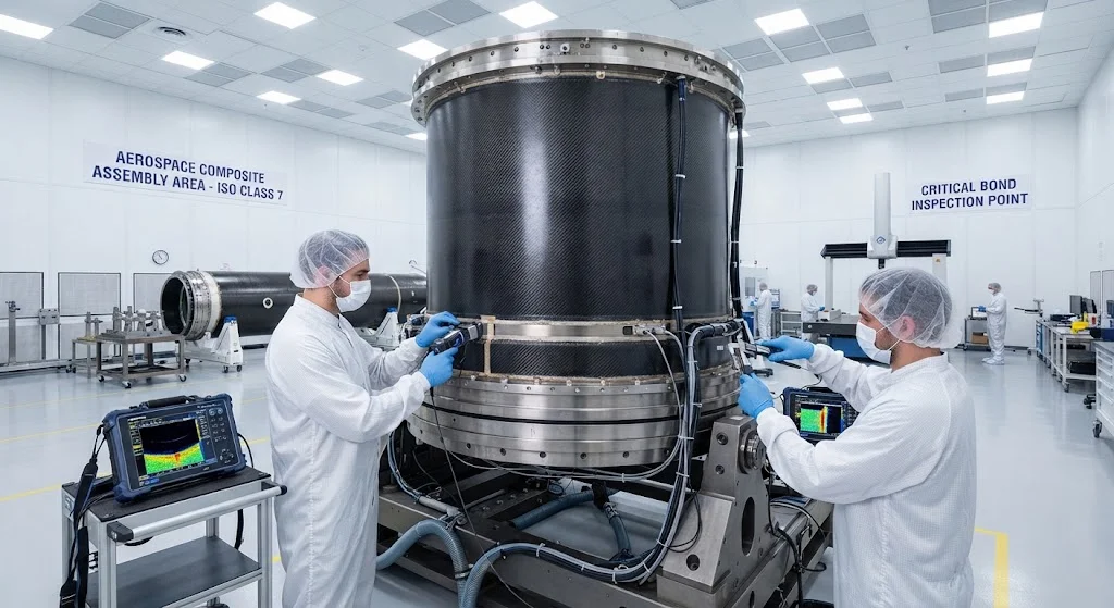
Carbon fiber composite interstage structures reduce launch vehicle weight while maintaining the structural integrity required for stage separation. This article covers design considerations, manufacturing methods, and performance benefits of CFRP interstages in modern rockets.
Introduction
The interstage structure — the cylindrical or conical section connecting rocket stages — is one of the most mass-sensitive components in a launch vehicle. Every kilogram saved in the interstage translates directly to increased payload capacity or reduced propellant requirements. Carbon fiber reinforced polymer (CFRP) composites have become the material of choice for modern interstage structures, offering 40–60% weight savings compared to aluminum alternatives while meeting the demanding structural requirements of launch environments.
The evolution from metallic to composite interstages began in the 1990s and has accelerated with the development of heavy-lift launch vehicles requiring extreme mass efficiency. Today, most new launch vehicle designs incorporate CFRP interstages as standard practice.
Design Requirements
Interstage structures must satisfy multiple, often competing requirements:
Compressive load bearing: During powered flight, the interstage carries the full thrust loads of the upper stage engine while supporting the mass of upper stage structures, propellant, and payload. Compressive loads can exceed 2,000 kPa in heavy-lift vehicles.
Bending stiffness: The interstage must resist lateral bending from aerodynamic loads, thrust misalignment, and maneuvering accelerations. Insufficient stiffness can cause flutter or control instability.
Stage separation: The interstage must separate cleanly and predictably when commanded, without generating debris that could damage the upper or lower stage. Separation is typically achieved through pyrotechnic devices, frangible joints, or mechanical release systems.
Thermal protection: During ascent through the atmosphere, aerodynamic heating can raise interstage skin temperatures to 200–400°C. The composite must maintain structural integrity at elevated temperatures while protecting internal components.
Vibration and acoustic loads: Launch environments produce extreme vibration and acoustic loads — often exceeding 140 dB — that can cause fatigue damage or component failure if not properly managed through structural design and damping.
Material Selection
CFRP interstage structures use specialized material systems optimized for the launch environment:
Fiber selection: Standard modulus carbon fiber (T300, T700) provides the best balance of cost and performance for most interstage applications. Intermediate modulus fibers (T800, IM7) are used where higher compressive strength is required. High modulus fibers (M55J, M60J) are reserved for stiffness-critical applications.
Resin systems: Toughened epoxy resins provide the best combination of mechanical properties, thermal resistance, and damage tolerance. Cyanate ester resins offer superior thermal stability for high-temperature applications. Bismaleimide (BMI) resins provide higher temperature capability than epoxies while maintaining processability.
Ply orientation: Interstage laminates typically use quasi-isotropic layups (0/±45/90°) for balanced properties, with local reinforcement at attachment points and load introduction regions. Thickness variations from 2–8 mm are common, with thicker laminates at high-stress locations.
Manufacturing Methods
Several manufacturing approaches are used for CFRP interstages:
Filament winding: Automated filament winding produces cylindrical and conical interstages with excellent fiber placement accuracy and high fiber volume fractions (55–65%). This method is well-suited for large-diameter interstages and provides consistent quality.
Automated fiber placement (AFP): AFP technology enables more complex geometries than filament winding, including non-circular cross-sections and local thickness variations. It is preferred for interstages with integrated features — attachment brackets, separation mechanisms, and thermal protection provisions.
Hand layup with autoclave cure: For smaller interstages or prototypes, hand layup followed by autoclave curing provides flexibility and high quality. However, the labor intensity makes this method less cost-effective for production volumes.
Performance Benefits
CFRP interstages provide measurable performance improvements over metallic alternatives:
Mass reduction: CFRP interstages typically weigh 40–60% less than aluminum equivalents, directly translating to increased payload capacity. For a heavy-lift vehicle, this mass savings can amount to hundreds of kilograms of additional payload.
Specific stiffness: CFRP's specific stiffness (stiffness-to-density ratio) is 2–3 times that of aluminum, enabling thinner walls and lower mass while maintaining required stiffness levels.
Thermal stability: CFRP's low coefficient of thermal expansion (CTE) minimizes dimensional changes during thermal cycling between ground and space environments, maintaining alignment of separation mechanisms and payload interfaces.
Damage tolerance: Well-designed CFRP interstages exhibit good damage tolerance, with progressive failure modes that provide warning before catastrophic failure — important for crewed vehicles.
Quality Assurance
Interstage structures require rigorous quality assurance:
Non-destructive inspection: Ultrasonic inspection, thermography, and X-ray CT scanning verify laminate quality — void content, fiber orientation, interlaminar bonding — before acceptance.
Structural testing: Full-scale structural testing validates design predictions and demonstrates margin of safety. Testing typically includes compression, bending, vibration, and acoustic load simulations.
Environmental testing: Thermal cycling, vibration, and acoustic testing verify interstage performance under simulated launch conditions.
Conclusion
Carbon fiber composite interstage structures are essential for maximizing launch vehicle performance. The combination of high specific stiffness, excellent compressive strength, and low density makes CFRP the optimal material for interstage applications. As launch vehicle designs continue to push the boundaries of payload capacity and cost efficiency, CFRP interstage technology will continue to evolve, enabling the next generation of space access vehicles.
Part of topic
Related Articles
- Carbon Fiber Mooring for Floating Offshore Wind: Fatigue and Corrosion in Deep Water
- Carbon Fiber Bicycle Frame Optimization: Layup Design and Manufacturing for Competitive Racing
- Carbon Fiber CFRP Retrofit for Infrastructure: Bridge and Building Seismic Strengthening
- Carbon Fiber Medical Imaging Equipment: Lightweight Gantry and Couch Structures for MRI/CT
- Carbon Fiber EV Battery Enclosures: Crash Safety and Electromagnetic Shielding Design
- Carbon Fiber Structures for Low-Altitude Economy: UAV Airframes and eVTOL Components
Interested in Our Products?
Contact our team for competitive pricing and technical specifications.
Get a QuoteRelated Products

Carbon Fiber Plate — 3K Twill T700 3.0mm
Medium-thickness 3.0mm carbon fiber plate offering significantly higher load capacity while maintaining attractive 3K twill finish. Suitable for structural brackets, reinforcement plates, and load-bearing panels.

Carbon Fiber Plate — 3K Twill T700 1.5mm
Thin 1.5mm carbon fiber plate with 3K twill weave surface. Lightweight and stiff, commonly used for covers, panels, drone bodies, and applications requiring a premium aesthetic appearance.

Square Carbon Fiber Tube — 3K Twill T700
Square cross-section carbon fiber tube manufactured with 3K twill weave for torsional strength. Preferred for structural frames, trusses, and support columns where rectangular geometry offers design flexibility.

Carbon Fiber Plate — UD Unidirectional T700
Unidirectional carbon fiber plate with all fibers oriented in a single direction for maximum strength along the fiber axis. Essential for structural reinforcements, splints, and applications where load direction is predictable.

Round Carbon Fiber Tube — UD Unidirectional T700
Unidirectional (UD) round tube with all fibers aligned axially for maximum longitudinal stiffness. Ideal for applications requiring high bending rigidity with minimal weight, such as shafts, struts, and structural reinforcements.