
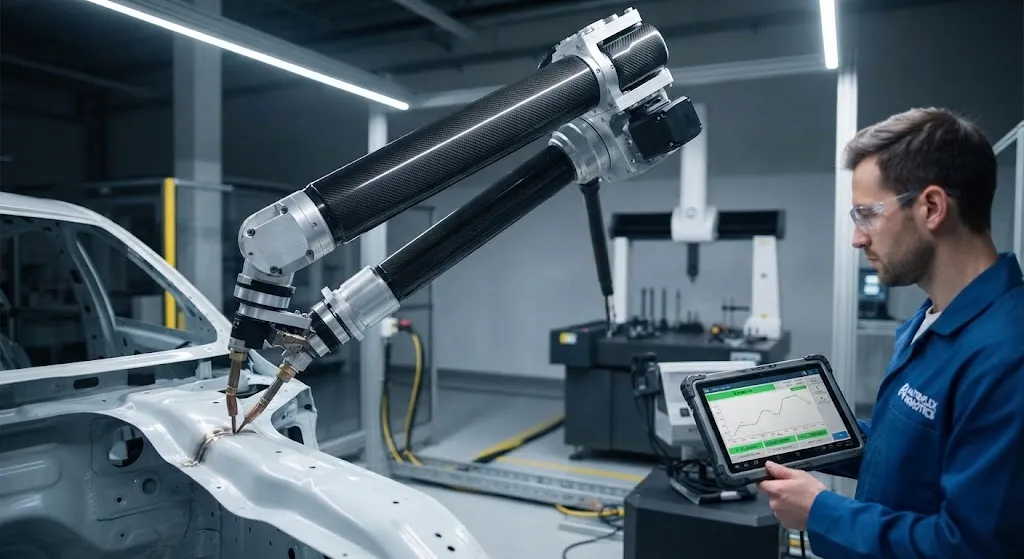
The push toward faster, more precise industrial automation has created strong demand for lighter robotic arm structures. In a six-axis articulated robot, the mass of each arm link directly affects the motor torque required for acceleration, the structural natural frequency that limits p
Introduction
The push toward faster, more precise industrial automation has created strong demand for lighter robotic arm structures. In a six-axis articulated robot, the mass of each arm link directly affects the motor torque required for acceleration, the structural natural frequency that limits positioning speed, and the vibration amplitude that degrades repeatability. Carbon fiber composite robotic arm structures address all three of these factors simultaneously by replacing aluminum or steel links with high-stiffness, low-density carbon fiber laminate or filament-wound tubes.
For robot integrators and factory automation engineers, the practical question is not whether carbon fiber is lighter — it obviously is — but whether the cost premium delivers measurable gains in cycle time, payload capacity, or positioning accuracy that justify the investment. This article quantifies those gains with concrete data, reviews the design approaches used in current carbon fiber robotic arm structures, and provides a framework for evaluating when carbon fiber makes engineering and economic sense in industrial automation applications.
Why Arm Mass Matters: The Physics of Articulated Robots
In an articulated robot, each motor must accelerate not only the payload at the end of the arm, but also every link and joint between the motor and the payload. The moment of inertia seen by each motor is proportional to the mass of the downstream links multiplied by the square of their distance from the motor axis. This means that reducing the mass of the outer arm links — the ones farthest from the base motors — has a disproportionate effect on required torque. The key relationships are:
- Torque requirement: Motor torque is proportional to arm link mass and acceleration. Halving the arm mass roughly halves the peak torque demand, or alternatively allows double the acceleration at the same torque.
- Natural frequency: The structural natural frequency of the arm scales with the square root of stiffness-to-mass ratio. Higher frequency means the arm settles faster after a move, reducing cycle time.
- Vibration and repeatability: Vibration amplitude is inversely proportional to natural frequency. A stiffer, lighter arm vibrates less, directly improving positioning repeatability.
- Energy consumption: Lower arm mass reduces the energy required per cycle, which over thousands of daily cycles translates to meaningful electricity savings and reduced motor heating.
Carbon fiber composite robotic arm structures offer stiffness-to-weight ratios of 3-5x that of aluminum, making them the material of choice for applications where speed, precision, and energy efficiency are all priorities.
Design Approaches for Carbon Fiber Robotic Arms
Carbon fiber robotic arm structures are manufactured using several approaches, each suited to different production volumes and performance requirements:
| Manufacturing Method | Typical Application | Wall Thickness | Fiber Volume Fraction | Relative Cost |
|---|---|---|---|---|
| Filament winding | Cylindrical arm tubes | 1.5-3.0 mm | 55-65% | Medium |
| Pultrusion | Straight structural members | 1.0-2.5 mm | 50-60% | Low |
| Prepreg autoclave | Complex-shaped arm links | 1.5-4.0 mm | 58-65% | High |
| RTM (resin transfer molding) | Integrated arm structures | 1.5-3.0 mm | 50-60% | Medium-High |
| Overwinding on aluminum core | Retrofit and hybrid designs | 0.5-1.5 mm | 45-55% | Low-Medium |
Most production carbon fiber robotic arm structures use a combination of these methods: filament-wound carbon fiber tubes for the main arm sections, with prepreg or RTM-molded fittings at the joint interfaces. The joint areas require complex geometry for bearing seats and motor mounting, which is difficult to achieve with winding alone. Adhesive bonding or mechanical fastening connects the carbon fiber tubes to the metal joint fittings.
Performance Gains: Measured Data
The performance advantages of carbon fiber robotic arm structures have been quantified in multiple published studies and commercial robot specifications. The following table summarizes typical improvements when replacing aluminum arm links with carbon fiber equivalents:
| Parameter | Aluminum Arm (Baseline) | Carbon Fiber Arm | Improvement |
|---|---|---|---|
| Arm link mass | 100% (baseline) | 40-55% | 45-60% reduction |
| Stiffness-to-weight ratio | 1.0x | 3.0-5.0x | 3-5x improvement |
| Natural frequency | 1.0x | 1.4-1.8x | 40-80% increase |
| Positioning repeatability | +/- 0.05 mm | +/- 0.02-0.03 mm | 40-60% improvement |
| Maximum acceleration | 1.0x | 1.5-2.0x | 50-100% increase |
| Payload-to-weight ratio | 1:3 to 1:5 | 1:2 to 1:3 | Significant improvement |
| Energy per cycle | 100% (baseline) | 55-75% | 25-45% reduction |
These gains compound across a six-axis robot: reducing the mass of the last three links (the wrist and forearm) affects three motors simultaneously, while reducing the first three links (upper arm and shoulder) affects up to six motors. The result is a robot that moves faster, stops more precisely, and consumes less energy — all from lighter arm structures.
Thermal Stability and Environmental Resistance
Beyond mechanical performance, carbon fiber robotic arm structures offer environmental advantages in demanding factory conditions:
- Thermal stability: Carbon fiber composites have a near-zero coefficient of thermal expansion (CTE) along the fiber direction, compared to 23 ppm/deg C for aluminum. In factories with temperature fluctuations of 10-20 deg C, aluminum arm links expand and contract measurably, causing thermal drift in positioning. Carbon fiber arms maintain dimensional stability, preserving accuracy through thermal cycles.
- Chemical resistance: Epoxy-based carbon fiber composites resist common industrial solvents, coolants, and lubricants that can degrade aluminum surfaces over time.
- Fatigue life: Carbon fiber composites exhibit excellent fatigue resistance, maintaining structural integrity through millions of cycles without the fretting and galling that can affect aluminum joint interfaces.
- Electrical insulation: Carbon fiber is electrically conductive, but the composite structure provides sufficient insulation for most automation applications. For applications requiring true electrical isolation, glass fiber hybrid layups are available.
Cost-Benefit Analysis for Factory Integration
The cost premium for carbon fiber robotic arm structures typically ranges from 2-4x the cost of equivalent aluminum arms. For high-value applications, the payback comes from multiple sources:
- Throughput increase: A 30-50% reduction in cycle time (from higher acceleration and faster settling) directly increases production output. For a robot performing 1,000 cycles per day, reducing cycle time from 4 seconds to 3 seconds adds 250 extra cycles — potentially 250 more parts per day.
- Payload increase: A lighter arm structure increases the net payload capacity. If the robot was payload-limited at 10 kg with aluminum arms, carbon fiber arms might allow 12-15 kg at the same speed — a 20-50% increase in useful payload.
- Accuracy improvement: Reduced vibration and thermal drift improve part quality, reducing scrap rates and rework costs. In precision assembly or dispensing applications, this alone can justify the material premium.
- Energy savings: 25-45% lower energy consumption per cycle adds up over the robot's 10-15 year service life, reducing operating costs.
The break-even point depends on application specifics, but for robots operating at high duty cycles in precision manufacturing, carbon fiber arms typically pay for themselves within 1-3 years.
Frequently Asked Questions
Can carbon fiber robotic arms be retrofitted to existing robots?
Yes, in many cases. Several manufacturers offer carbon fiber arm upgrade kits for popular robot models. The retrofit typically involves replacing aluminum arm tubes with carbon fiber equivalents while retaining the original joint bearings and motor mounts. The robot controller may need re-tuning to account for the changed arm dynamics (lower inertia, higher natural frequency), but no hardware modifications to the motors or drives are usually required. Some integrators also offer overwinding services, where carbon fiber is wound directly onto existing aluminum arm structures to add stiffness without full replacement.
How do carbon fiber arms handle impact damage compared to aluminum?
Carbon fiber composites respond differently to impact than aluminum. Aluminum deforms plastically, absorbing energy through permanent bending — the arm is visibly damaged but often still functional. Carbon fiber composites may show less visible damage from the same impact but could have internal delamination that reduces strength. For robotic applications, this means impact protection design must account for the different failure mode. Many carbon fiber arm designs include energy-absorbing features at exposed locations, and routine ultrasonic inspection can detect subsurface damage that is not visible to the eye.
What is the typical service life of carbon fiber robotic arms?
Carbon fiber robotic arm structures typically match or exceed the service life of the robot itself, which is commonly 8-15 years or 50,000-100,000 operating hours. The composite material does not fatigue in the same way as metals, and proper design ensures that stress levels remain well below the fatigue endurance limit throughout the service life. The limiting factor is usually bearing wear at the joints rather than structural degradation of the carbon fiber arm itself. Many carbon fiber arms have been documented lasting 20+ years in continuous industrial service.
Conclusion
Carbon fiber robotic arm structures deliver a compelling combination of reduced inertia, increased stiffness, and improved thermal stability that translates directly into faster cycle times, higher payloads, and better positioning accuracy for industrial automation. With stiffness-to-weight ratios 3-5x that of aluminum and cycle time improvements of 30-50%, carbon fiber arms represent a proven upgrade path for high-duty-cycle precision manufacturing applications. The 2-4x cost premium is recovered through throughput gains, payload increases, and energy savings, typically within 1-3 years of operation.
For engineers evaluating carbon fiber robotic arm structures for their automation lines, explore our carbon fiber tube and structural profile range, including filament-wound and pultruded options optimized for robotic applications, or contact our engineering team to discuss arm design, material selection, and performance modeling for your specific robot platform.
Part of topic
Related Articles
- Carbon Fiber Mooring for Floating Offshore Wind: Fatigue and Corrosion in Deep Water
- Carbon Fiber Bicycle Frame Optimization: Layup Design and Manufacturing for Competitive Racing
- Carbon Fiber CFRP Retrofit for Infrastructure: Bridge and Building Seismic Strengthening
- Carbon Fiber Medical Imaging Equipment: Lightweight Gantry and Couch Structures for MRI/CT
- Carbon Fiber EV Battery Enclosures: Crash Safety and Electromagnetic Shielding Design
- Carbon Fiber Structures for Low-Altitude Economy: UAV Airframes and eVTOL Components
Interested in Our Products?
Contact our team for competitive pricing and technical specifications.
Get a QuoteRelated Products

Carbon Fiber Plate — 3K Twill T700 1.5mm
Thin 1.5mm carbon fiber plate with 3K twill weave surface. Lightweight and stiff, commonly used for covers, panels, drone bodies, and applications requiring a premium aesthetic appearance.

Carbon Fiber Plate — 3K Twill T700 3.0mm
Medium-thickness 3.0mm carbon fiber plate offering significantly higher load capacity while maintaining attractive 3K twill finish. Suitable for structural brackets, reinforcement plates, and load-bearing panels.

Square Carbon Fiber Tube — 3K Twill T700
Square cross-section carbon fiber tube manufactured with 3K twill weave for torsional strength. Preferred for structural frames, trusses, and support columns where rectangular geometry offers design flexibility.

Carbon Fiber Plate — UD Unidirectional T700
Unidirectional carbon fiber plate with all fibers oriented in a single direction for maximum strength along the fiber axis. Essential for structural reinforcements, splints, and applications where load direction is predictable.

Round Carbon Fiber Tube — UD Unidirectional T700
Unidirectional (UD) round tube with all fibers aligned axially for maximum longitudinal stiffness. Ideal for applications requiring high bending rigidity with minimal weight, such as shafts, struts, and structural reinforcements.