
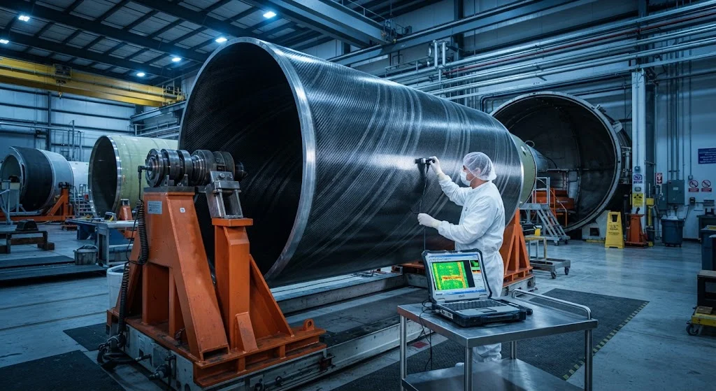
Reusable rocket programs require lightweight composite propellant tanks that withstand multiple thermal cycles and deep-throttle engine operations. This article covers CFRP tank design, qualification testing, and operational experience from commercial launch vehicles.
Introduction
The shift toward reusable launch vehicles has created new requirements for composite propellant tanks. Unlike expendable rockets where tanks are discarded after a single flight, reusable vehicles require tanks that maintain structural integrity through multiple thermal cycles, pressure cycles, and mechanical loads over dozens to hundreds of flights.
Carbon fiber reinforced polymer (CFRP) composite tanks offer 30-40% weight savings over aluminum equivalents, directly translating to increased payload capacity or reduced propellant requirements. However, the reusability requirement introduces additional design challenges related to fatigue life, thermal cycling resistance, and micrometeorite damage tolerance.
Design Requirements
Reusable composite propellant tanks must satisfy demanding requirements:
Multi-cycle fatigue: Tanks must withstand 100+ pressure cycles from empty to full load, with each cycle involving thermal gradients from cryogenic propellant temperatures (-253°C for liquid hydrogen, -183°C for liquid oxygen) to aerodynamic heating during ascent.
Deep-throttle compatibility: Reusable first-stage engines throttle deeply (30-100% thrust) for controlled descent, creating variable pressure loads on propellant tanks. The tank structure must accommodate these pressure variations without excessive deformation or stress.
Thermal cycling: Tanks experience extreme thermal cycling between missions — from cryogenic propellant temperatures during flight to ambient temperatures on the ground. This cycling can cause matrix microcracking, delamination, and reduced stiffness if not properly managed.
Damage tolerance: Reusable vehicles must tolerate minor damage from micrometeorites, debris, and handling without requiring extensive inspection or repair between flights.
Material Systems
Reusable composite tanks use specialized material systems:
Fiber selection: Intermediate modulus carbon fibers (IM7, T800) provide the best balance of strength, stiffness, and strain capability for reusable tank applications. High strain-to-failure (>1.5%) is critical for accommodating thermal cycling stresses.
Resin systems: Toughened epoxy resins with high glass transition temperature (Tg > 180°C) and low moisture absorption are standard. Cyanate ester resins offer superior thermal stability for high-temperature applications. Both must demonstrate minimal microcracking after cryogenic thermal cycling.
Barrier coatings: Internal liner systems — either metallic (aluminum or stainless steel) or polymeric (epoxy-novolac) — provide permeability barriers for cryogenic propellants. The liner must accommodate differential thermal expansion between the CFRP structure and the propellant.
Manufacturing Processes
Reusable composite tanks are manufactured using specialized processes:
Filament winding: Automated filament winding produces cylindrical and domed tank sections with high fiber volume fractions (55-65%). Multi-axis winding patterns optimize fiber orientation for combined pressure, axial, and bending loads.
Cure cycle optimization: Multi-step cure cycles with controlled ramp rates and dwell times minimize residual stresses that can cause microcracking during cryogenic thermal cycling. Post-cure treatments at elevated temperatures further improve thermal stability.
Non-destructive evaluation: Comprehensive ultrasonic inspection, thermography, and X-ray CT scanning verify laminate quality before acceptance. Any detected defects must be repaired or the component rejected.
Qualification Testing
Reusable tank qualification requires extensive testing beyond single-use requirements:
Multi-cycle pressure testing: Tanks undergo 2-3x the planned number of pressure cycles at design load to demonstrate fatigue life margin. Cryogenic thermal cycling is performed between pressure cycles to simulate operational conditions.
Burst testing: Proof burst testing at 1.5x design pressure demonstrates structural margin. Burst pressure must exceed the maximum expected operating pressure with adequate safety factor.
Thermal cycling testing: Tanks are subjected to hundreds of cryogenic thermal cycles to verify that matrix microcracking, delamination, and stiffness degradation remain within acceptable limits throughout the planned service life.
Operational Experience
Commercial reusable launch vehicles have demonstrated the viability of composite propellant tanks:
Flight heritage: Multiple commercial operators have accumulated hundreds of flights with composite tanks, demonstrating that proper design and manufacturing can achieve the reliability and reusability requirements of commercial space operations.
Inspection intervals: Operational experience has established inspection intervals and acceptance criteria for reusable composite tanks, enabling efficient turnaround between flights while maintaining safety margins.
Repair procedures: Standardized repair procedures for minor damage — surface abrasions, small delaminations, and liner defects — enable rapid return to service without compromising structural integrity.
Conclusion
Reusable rocket composite propellant tanks represent a mature technology that enables the weight savings and performance benefits of CFRP in commercial space applications. As reusable launch vehicle operations scale up, composite tank technology will continue to evolve, with improvements in durability, inspection efficiency, and manufacturing cost reduction supporting the growth of commercial space transportation.
Part of topic
Related Articles
- Carbon Fiber Mooring for Floating Offshore Wind: Fatigue and Corrosion in Deep Water
- Carbon Fiber Bicycle Frame Optimization: Layup Design and Manufacturing for Competitive Racing
- Carbon Fiber CFRP Retrofit for Infrastructure: Bridge and Building Seismic Strengthening
- Carbon Fiber Medical Imaging Equipment: Lightweight Gantry and Couch Structures for MRI/CT
- Carbon Fiber EV Battery Enclosures: Crash Safety and Electromagnetic Shielding Design
- Carbon Fiber Structures for Low-Altitude Economy: UAV Airframes and eVTOL Components
Interested in Our Products?
Contact our team for competitive pricing and technical specifications.
Get a QuoteRelated Products

Carbon Fiber Plate — 3K Twill T700 3.0mm
Medium-thickness 3.0mm carbon fiber plate offering significantly higher load capacity while maintaining attractive 3K twill finish. Suitable for structural brackets, reinforcement plates, and load-bearing panels.

Carbon Fiber Plate — 3K Twill T700 1.5mm
Thin 1.5mm carbon fiber plate with 3K twill weave surface. Lightweight and stiff, commonly used for covers, panels, drone bodies, and applications requiring a premium aesthetic appearance.

Square Carbon Fiber Tube — 3K Twill T700
Square cross-section carbon fiber tube manufactured with 3K twill weave for torsional strength. Preferred for structural frames, trusses, and support columns where rectangular geometry offers design flexibility.

Carbon Fiber Plate — UD Unidirectional T700
Unidirectional carbon fiber plate with all fibers oriented in a single direction for maximum strength along the fiber axis. Essential for structural reinforcements, splints, and applications where load direction is predictable.

Round Carbon Fiber Tube — UD Unidirectional T700
Unidirectional (UD) round tube with all fibers aligned axially for maximum longitudinal stiffness. Ideal for applications requiring high bending rigidity with minimal weight, such as shafts, struts, and structural reinforcements.