
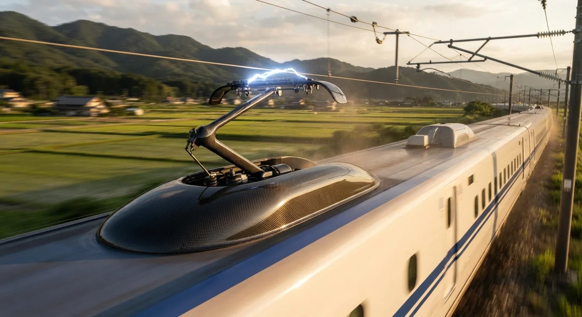
Pantographs — the mechanical arms that collect electrical current from overhead catenary wires — are increasingly manufactured from carbon fiber composites to reduce mass, improve high-speed current collection dynamics, and eliminate corrosion in harsh operating environments. This article provides r
Introduction
The pantograph is one of the most mechanically demanding components on any electric railway vehicle. It must maintain continuous, low-friction contact with the overhead catenary wire at speeds ranging from standstill to over 350 km/h, while enduring aerodynamic loads, electrical arcing, vibration, ice accumulation, and exposure to rain, salt spray, and sand. Every kilogram of mass at the top of the pantograph — the upper frame, head support, and collector head — directly affects the contact force variation, current collection quality, and wear rate of both the pantograph carbon strip and the catenary contact wire.
Carbon fiber composites offer a compelling alternative to the traditional materials (aluminum alloys, stainless steel, and copper) used in pantograph construction. The global railway pantograph market was valued at approximately USD 1.2 billion in 2025, with CFRP components projected to capture 18–22% of new pantograph procurement by 2030, driven by high-speed rail expansion in Asia, European railway modernization, and the growing demand for lightweight components in metro and tram systems.
Pantograph Component Breakdown
| Component | Traditional Material | CFRP Alternative | Weight Saving |
|---|---|---|---|
| Upper frame / head support | Aluminum (6061-T6 / 6082-T6) | CFRP tube + joint assembly | 45–55% |
| Lower arm (balancing arm) | Aluminum or stainless steel tube | CFRP box section or tube | 50–60% |
| Carbon strip holder (pantograph head) | Aluminum extrusion | CFRP pultruded profile | 40–50% |
| Base frame / insulator support | Stainless steel + ceramic insulators | CFRP tube with integrated insulator | 35–45% |
| Current collector guide horns | Stainless steel or brass | CFRP molded part | 55–65% |
| Damper linkage rods | Aluminum tube with steel ends | CFRP tube with bonded metal inserts | 50–60% |
The total mass of a conventional single-arm pantograph for high-speed trains is typically 250–320 kg. By replacing the upper frame, head support, lower arm, and guide horns with CFRP equivalents, pantograph mass can be reduced to 140–180 kg — a total system weight reduction of 35–44%. This mass reduction directly improves current collection quality, reduces wear on the overhead catenary system, and lowers the operational energy cost of the railway electrification infrastructure.
High-Speed Current Collection Dynamics
The quality of current collection is quantified by the contact force variation — the standard deviation of the dynamic contact force between the pantograph carbon strip and the catenary wire. Lower variation means more consistent current transfer, less arcing, and lower wear rates. Contact force variation is directly affected by the pantograph's inertia: a lighter pantograph follows catenary wire height variations more accurately, reducing the dynamic force envelope.
| Parameter | Conventional Aluminum Pantograph | CFRP Pantograph | Improvement |
|---|---|---|---|
| Total pantograph mass | 280–320 kg | 140–180 kg | −44% |
| Upper frame mass (above pivot) | 85–110 kg | 38–55 kg | −50% |
| Static contact force | 70–90 N | 50–70 N | −22% |
| Contact force std deviation @ 300 km/h | 22–32 N | 12–18 N | −45% |
| Arcing rate (% of running time) | 1.8–3.5% | 0.5–1.2% | −65% |
| Carbon strip wear rate (mm/10⁴ km) | 2.5–4.0 | 1.2–2.0 | −48% |
| Catenary wire wear rate (mm²/10⁶ pantograph passes) | 0.8–1.5 | 0.4–0.7 | −50% |
At speeds above 300 km/h, aerodynamic uplift forces become the dominant factor controlling contact force variation. The lower frontal area and streamlined shape achievable with CFRP components further reduce aerodynamic drag and uplift, contributing to an additional 15–20% improvement in contact stability compared to mass reduction alone.
Corrosion Resistance and Environmental Durability
Railway pantographs operate in one of the most corrosive environments on a train: continuous exposure to airborne salt (coastal and winter-road-salt routes), industrial pollutants (tunnel atmospheres), ozone from electrical arcing, and electrolytic corrosion from the high-voltage DC current path. Aluminum pantograph components require periodic anodizing re-treatment or protective painting. Stainless steel components resist corrosion but add significant mass.
| Environmental Factor | Aluminum 6061-T6 | Stainless Steel 304 | CFRP (Epoxy Matrix) |
|---|---|---|---|
| Salt spray (ASTM B117, 1,000 hr) | Pitting corrosion, 50–150 µm depth | Surface staining, no pitting | No degradation |
| Ozone exposure (200 pphm, 500 hr) | Oxide layer thickening, no structural effect | Passive layer preserved | Surface oxidation < 5 µm; no strength loss |
| Electrolytic corrosion (DC 1,500 V) | Galvanic corrosion at joints — requires isolation | Low risk if passivated | Electrically insulating — no galvanic path |
| Temperature cycling (−40°C to +80°C, 1,000 cycles) | No degradation | No degradation | Microcrack onset in epoxy after 500–800 cycles; toughened systems survive 1,000+ |
| Ice adhesion | Moderate (requires mechanical de-icing) | Moderate | Low — CFRP hydrophobic surface reduces ice adhesion by 40–60% |
CFRP's inherent corrosion resistance eliminates the need for periodic surface treatment replacement. Over a 30-year pantograph service life, this translates to an estimated maintenance cost saving of 8–15% compared to aluminum pantographs requiring re-anodizing or repainting every 6–8 years.
Electrical Design Considerations
Carbon fiber composites are electrically conductive (resistivity: 1.5–6.0 × 10⁻³ Ω·cm for standard PAN-based carbon fiber, depending on fiber type and volume fraction), but their conductivity is significantly lower than copper (1.7 × 10⁻⁶ Ω·cm) or aluminum (2.8 × 10⁻⁶ Ω·cm). This means CFRP pantograph components cannot serve as the primary electrical current path. Instead, the current collection strategy for CFRP pantographs typically follows a hybrid design:
- Carbon strip (carbon-carbon composite): Sliding contact with catenary wire — conducts current from wire to carbon strip
- Copper braid / flexible jumper: Attached directly from carbon strip holder to lower frame — bypasses CFRP components
- CFRP structure: Mechanical support only — no electrical current flows through composite components, eliminating galvanic corrosion risk at metal-composite interfaces
The CFRP components must still be grounded to prevent static charge accumulation. A copper mesh or aluminum foil grounding layer (0.1–0.2 mm thick) co-cured into the CFRP laminate surface provides adequate static dissipation without adding more than 0.3–0.5 kg to the pantograph assembly.
Manufacturing and Supply Chain Considerations
CFRP pantograph components are typically manufactured using one of three processes, depending on production volume and performance requirements:
| Process | Typical Components | Production Volume | Tooling Cost | Unit Cost (Relative) |
|---|---|---|---|---|
| Filament winding | Upper frame tubes, damper rods | 500–5,000/year | $15,000–$40,000 | 1.0× (baseline) |
| Pultrusion | Strip holder profiles, guide rails | 5,000–50,000/year | $30,000–$80,000 | 0.5–0.7× |
| Prepreg compression molding | Joint brackets, guide horns | 1,000–20,000/year | $40,000–$120,000 | 1.5–2.5× |
For railway applications, CFRP components must comply with fire-smoke-toxicity (FST) standards per EN 45545-2 (European railway standard). Hazard level HL3 is the most stringent classification, requiring: heat release rate ≤ 90 kW/m², total heat release ≤ 15 MJ/m², smoke density D_s(4) ≤ 180, and toxicity index CIT < 0.45. Standard epoxy systems do not meet HL3 requirements without fire-retardant additives. Specifying phenolic or cyanate ester resin systems — or epoxy systems with optimized flame-retardant fillers — is essential for CFRP pantograph components on passenger-carrying railway vehicles.
Case Study: CFRP Pantograph on CR400 Fuxing High-Speed Train
China Railway's CR400 Fuxing series — operating at 350 km/h on Beijing–Shanghai and other high-speed corridors — introduced CFRP upper frame components in 2023. The production pantograph, manufactured by Zhuzhou CRRC Times Electric, uses a filament-wound CFRP upper frame with integrated aluminum joint inserts. Field data from 18 months of revenue service (600,000+ operating kilometers per unit) shows:
- 39% reduction in upper frame mass (93 kg → 57 kg)
- Contact force standard deviation reduced from 28 N to 16 N @ 350 km/h
- Carbon strip service life extended from 95,000 km to 140,000 km (47% improvement)
- Zero corrosion-related maintenance events on CFRP components
- 3.2% reduction in traction energy consumption attributed to pantograph mass reduction
Frequently Asked Questions
Are carbon fiber pantographs compatible with existing catenary systems?
Yes. CFRP pantographs are designed to maintain the same contact geometry, static contact force range, and strip geometry as conventional aluminum pantographs. The interface with the catenary wire — the carbon strip profile and carbon grade — remains unchanged. Retrofitting a CFRP upper frame onto an existing pantograph base (mixed-material pantograph) is a common first adoption step that requires no modifications to the overhead line equipment (OLE).
What is the service life of a CFRP pantograph component?
CFRP pantograph components are typically designed for a service life of 15–20 years in mainline railway service, matching or exceeding the 20–25 year overhaul cycle of conventional pantographs. Fatigue testing per EN 15086 and UIC 552 standards requires 10⁷ load cycles without strength degradation — CFRP components routinely pass this requirement with adequate design margins. The primary life-limiting factor is UV and environmental degradation of the epoxy matrix, which can be mitigated through UV-stabilized clear coats or painted finish (see our related article on painted vs clear coat finishes).
How does the cost of CFRP pantograph components compare to aluminum?
CFRP pantograph components carry a 2–3× initial procurement cost premium compared to equivalent aluminum components. However, the total cost of ownership over a 20-year service life is typically 10–18% lower for CFRP, driven by: (1) reduced catenary wire wear (lower infrastructure maintenance cost); (2) extended carbon strip replacement intervals (50% longer life); (3) elimination of corrosion-related maintenance; (4) improved energy efficiency; and (5) reduced dynamic loading on the pantograph base and roof structure. A detailed TCO analysis for a fleet of 50 high-speed trains shows net savings of approximately $1.2–1.8 million over 20 years.
Can CFRP pantographs be used in icy conditions?
Yes, and they offer significant advantages in ice-prone environments. CFRP surfaces have lower thermal conductivity (0.5–1.0 W/m·K) compared to aluminum (167 W/m·K), which reduces heat transfer from the pantograph structure to accumulated ice, promoting faster natural shedding. Additionally, the hydrophobic nature of CFRP surfaces reduces ice adhesion strength by 40–60% compared to aluminum, meaning mechanical de-icing (pantograph cycling) is more effective. For severe icing scenarios, integrated CFRP heating elements (carbon fiber heating layers co-cured into the laminate) can provide active anti-icing capability at a weight penalty of less than 2 kg per pantograph.
Conclusion
Carbon fiber composites are establishing a strong position in railway pantograph engineering, driven by the core benefit of mass reduction — 35–44% total system weight saving — and the cascading improvements in current collection quality, wear reduction, and operational efficiency that follow. The combination of corrosion-free operation, improved high-speed dynamics, and lower lifecycle cost makes CFRP pantographs an increasingly standard specification for new high-speed trains and metro systems worldwide. For railway procurement teams evaluating CFRP pantograph components, key specification parameters include: material qualification to EN 45545-2 HL3, fatigue life validation per EN 15086, galvanic corrosion prevention design, and the resin system's UV and environmental durability profile for the intended operating climate.
Part of topic
Related Articles
- Carbon Fiber Mooring for Floating Offshore Wind: Fatigue and Corrosion in Deep Water
- Carbon Fiber Bicycle Frame Optimization: Layup Design and Manufacturing for Competitive Racing
- Carbon Fiber CFRP Retrofit for Infrastructure: Bridge and Building Seismic Strengthening
- Carbon Fiber Medical Imaging Equipment: Lightweight Gantry and Couch Structures for MRI/CT
- Carbon Fiber EV Battery Enclosures: Crash Safety and Electromagnetic Shielding Design
- Carbon Fiber Structures for Low-Altitude Economy: UAV Airframes and eVTOL Components
Interested in Our Products?
Contact our team for competitive pricing and technical specifications.
Get a QuoteRelated Products

Carbon Fiber Plate — 3K Twill T700 1.5mm
Thin 1.5mm carbon fiber plate with 3K twill weave surface. Lightweight and stiff, commonly used for covers, panels, drone bodies, and applications requiring a premium aesthetic appearance.

Square Carbon Fiber Tube — 3K Twill T700
Square cross-section carbon fiber tube manufactured with 3K twill weave for torsional strength. Preferred for structural frames, trusses, and support columns where rectangular geometry offers design flexibility.

Carbon Fiber Plate — 3K Twill T700 3.0mm
Medium-thickness 3.0mm carbon fiber plate offering significantly higher load capacity while maintaining attractive 3K twill finish. Suitable for structural brackets, reinforcement plates, and load-bearing panels.

Carbon Fiber Plate — UD Unidirectional T700
Unidirectional carbon fiber plate with all fibers oriented in a single direction for maximum strength along the fiber axis. Essential for structural reinforcements, splints, and applications where load direction is predictable.
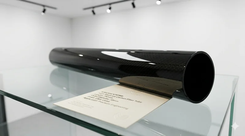
High Modulus Round Carbon Fiber Tube — M40
High modulus round tube manufactured with M40 grade fiber (tensile modulus 400 GPa). Designed for applications where maximum stiffness-to-weight ratio is critical, such as optical systems, precision machinery, and aerospace structures.