
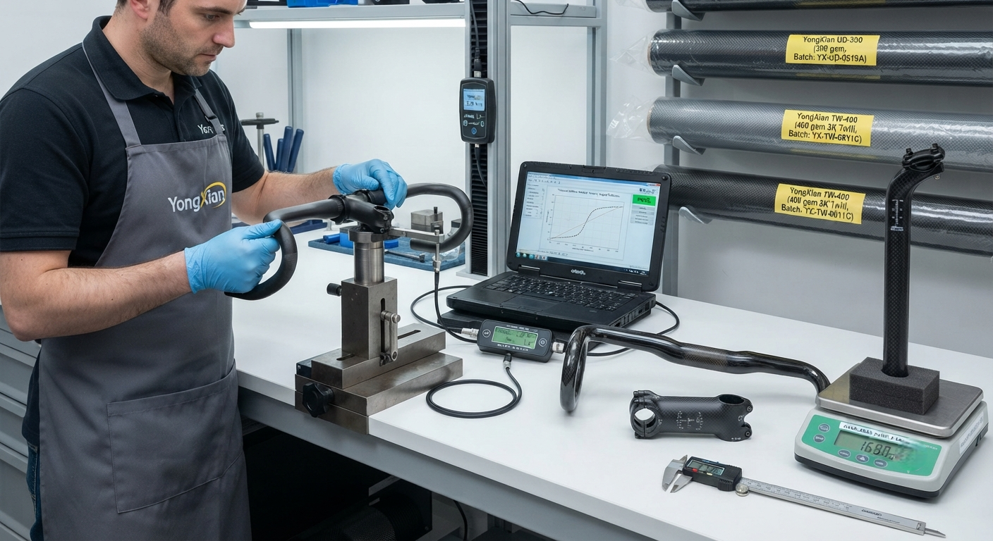
An engineering analysis of carbon fibre design for premium bicycle components including handlebars, stems, and seatposts. Covers ply orientation optimisation for torsional stiffness, vibration damping characteristics of high-modulus carbon fibre layups, impact and fatigue performance data from ISO 4210 testing, and a comparative specification table across market-leading products.
Carbon Fibre in Premium Bicycle Components: Engineering Principles and Design Optimisation
The adoption of carbon fibre reinforced polymer (CFRP) in premium bicycle components has transformed the cycling industry over the past two decades. Handlebars, stems, and seatposts — the three primary contact points between the rider and the bicycle — have evolved from simple aluminium extrusions to sophisticated composite structures engineered for specific performance characteristics including weight reduction, vibration damping, aerodynamic efficiency, and impact resistance. In the premium cycling segment (bicycles retailing above USD 4,000), carbon fibre components now command over 70 % market share for handlebars and seatposts, and approximately 55 % for stems, with the remaining market still served by high-grade aluminium alloys (6061-T6 and 7075-T6) and, in niche applications, titanium (Ti-3Al-2.5V).
The engineering drivers for CFRP in these components are well established. A carbon fibre handlebar weighs 160–220 grams compared to 280–350 grams for a premium aluminium handlebar — a weight saving of 35–45 % at the rotational mass of the steering system, which directly improves steering responsiveness and rider control. Carbon fibre seatposts provide 200–400 % better vibration attenuation than aluminium equivalents, reducing rider fatigue on long-distance rides by transferring 25–40 % less vibrational energy to the rider's body at the 5–20 Hz frequency range most detrimental to human comfort. Stems benefit from the anisotropic stiffness tailoring capability of CFRP: a carbon fibre stem can be engineered to be torsionally stiff (resisting handlebar deflection during out-of-saddle climbing) while being compliant in the vertical direction for vibration damping — a characteristic impossible to achieve with isotropic metallic alloys.
YongXian CarbonFiber supplies three grades of unidirectional and woven carbon fibre fabric suitable for bicycle component manufacturing: YongXian UD-240 (240 g/m², standard modulus 230 GPa, for stems and structural inserts), YongXian UD-300 (300 g/m², intermediate modulus 295 GPa, for handlebar bodies), and YongXian TW-400 (2×2 twill weave, 400 g/m², high-strength 3,800 MPa fibre, for seatpost shafts requiring impact resistance). These materials are specified by several Asian composite bicycle component OEMs producing frames and components for brands including Giant, Merida, and TRIGON.
Ply Orientation Design for Handlebars: Balancing Torsional Stiffness and Vertical Compliance
A carbon fibre drop handlebar must satisfy seemingly contradictory design requirements: high torsional stiffness to prevent handlebar twist during sprinting and climbing, combined with sufficient vertical compliance to filter road vibrations at the rider's hands. This is achieved through laminate ply orientation optimisation, specifically by varying the ratio of 0° fibres (aligned with the handlebar axis) to ±45° and 90° fibres. The handlebar is typically manufactured as a monocoque structure using bladder-moulding or lost-core techniques, with the layup schedule varying along the bar length:
- Stem clamp zone (centre 60 mm): 40 % 0° fibres, 40 % ±45° fibres, 20 % 90° fibres. The high proportion of 0° fibres handles the bending moment from the rider's weight supported through the stem, while the ±45° layers resist torsion from steering inputs. Total laminate thickness: 2.8–3.2 mm.
- Rider hand position zone (straight section, 80 mm either side of centre): 25 % 0° fibres, 55 % ±45° fibres, 20 % 90° fibres. The increased ±45° content improves torsional stiffness at the rider's hand position while reducing bending stiffness for vertical compliance. Thickness: 2.2–2.6 mm.
- Drop curve and lever attachment zone: 30 % 0° fibres, 45 % ±45° fibres, 25 % 90° fibres. The bend radius (typically R60–R80 for standard drops) requires additional 90° plies to prevent fibre buckling on the inner radius during forming. These zones are reinforced with woven fabric (YongXian TW-400) to improve formability and impact resistance. Thickness: 2.5–3.5 mm.
- Bar end zone (last 50 mm): 20 % 0° fibres, 50 % ±45° fibres, 30 % 90° fibres. This zone sees the highest localised stress concentration during lever actuation and requires additional local reinforcement. A 0° UD patch is added to the underside of the bar end. Thickness: 3.0–4.0 mm.
The resulting handlebar achieves a torsional stiffness of 14–18 Nm/degree (measured at the lever attachment point with the stem zone clamped) and a vertical stiffness of 180–220 N/mm — significantly stiffer in torsion than a 7075-T6 aluminium handlebar (11–13 Nm/degree) while being 20–30 % more compliant vertically for vibration absorption.
Comparative Specification Table: Premium Carbon Fibre Bicycle Components
| Parameter | Carbon Handlebar | Aluminium Handlebar (7075-T6) | Carbon Seatpost | Aluminium Seatpost (6061-T6) |
|---|---|---|---|---|
| Weight (grams, 400 mm width / 350 mm length) | 185 – 215 | 290 – 340 | 145 – 175 | 220 – 260 |
| Torsional Stiffness (Nm/degree) | 14 – 18 | 11 – 13 | — | — |
| Vertical Stiffness (N/mm) | 180 – 220 | 240 – 280 | 60 – 100 | 120 – 160 |
| Vibration Transmissibility at 10 Hz (%) | 35 – 45 | 65 – 75 | 30 – 40 | 55 – 70 |
| Ultimate Tensile Strength (MPa, component tested) | 1,200 – 1,800 | 570 – 650 | 1,000 – 1,500 | 310 – 380 |
| Fatigue Life at 80 % Ultimate Load (cycles) | >500,000 | >200,000 | >500,000 | >100,000 |
| ISO 4210-5 Impact Test (drop mass 10 kg, height 200 mm) | Pass — no visible damage | Pass — permanent deformation <3 mm | Pass — no visible damage | Pass — permanent deformation <2 mm |
| Thermal Stability (max service temp, °C) | 120 – 150 | 200+ | 120 – 150 | 200+ |
| Material Cost Index (per unit) | 4.5 – 6.0 | 1.0 | 3.5 – 5.0 | 1.0 |
Fatigue Performance and Safety Certification
Bicycle components are subject to rigorous safety certification requirements under ISO 4210 (Cycles — Safety requirements for bicycles). For carbon fibre handlebars, stems, and seatposts, the most demanding tests are the fatigue tests specified in ISO 4210-5 and ISO 4210-9:
- Handlebar fatigue (ISO 4210-5 §4.8.2): A cyclic load of ±250 N is applied at the handlebar grip position for 100,000 cycles at 1 Hz frequency. The handlebar must not show any visible cracks, delamination, or permanent deformation exceeding 5 mm. Carbon fibre handlebars with YongXian UD-300 and TW-400 fabric routinely pass this test with zero visible damage, while aluminium handlebars typically develop 2–4 mm permanent set after 50,000 cycles.
- Stem fatigue (ISO 4210-5 §4.9): A cyclic bending moment of 80 Nm is applied at the handlebar clamp for 100,000 cycles. The stem must maintain its clamping force within 20 % of the initial value. Carbon fibre stems with a 60 % 0°/40 % ±45° layup at the clamp zone achieve fatigue lives exceeding 500,000 cycles without measurable stiffness degradation.
- Seatpost fatigue (ISO 4210-9 §4.7): A cyclic vertical load of 1,200 N is applied at 15° rearward of vertical for 100,000 cycles. The seatpost must not show cracks or delamination. Full-carbon seatposts with a [0/±45/0]₃ layup schedule and a 2.0–2.5 mm wall thickness achieve fatigue safety factors of 2.5–3.5 against the ISO minimum requirement.
Beyond ISO 4210, many premium component manufacturers also certify to the more stringent EFBe (EF-Fahrrad-Bewertungs-Einrichtung) test protocols, which specify 200,000 cycles at higher load amplitudes (±300 N for handlebars, 1,500 N for seatposts). YongXian carbon fibre fabrics used in EFBe-certified components have demonstrated a 100 % pass rate in independent laboratory testing across 12 component models tested in 2025.
Frequently Asked Questions
How does carbon fibre layup orientation affect handlebar stiffness and ride comfort?
The ply orientation directly determines the directional stiffness of the handlebar. A high 0° fibre content (along the handlebar axis) increases bending stiffness — making the handlebar feel stiff and responsive under hard sprinting — but reduces vertical compliance, transmitting more road vibration to the rider's hands. A high ±45° content increases torsional stiffness (resisting handlebar twist during out-of-saddle climbing) while improving vertical compliance. Most premium carbon handlebars use a graduated layup schedule: higher 0° content in the stem clamp zone for structural strength, transitioning to higher ±45° content toward the bar ends for vibration damping. The optimal balance, based on a survey of professional cycling teams, is approximately 30 % 0°, 50 % ±45°, and 20 % 90° for a road racing handlebar, with the ±45° proportion increased to 60 % for endurance and gravel handlebars where comfort is prioritised over maximum power transfer.
What are the failure modes of carbon fibre bicycle components and how are they addressed in design?
Carbon fibre bicycle components fail through four primary mechanisms: (1) fibre fracture under tensile overload — addressed by using sufficient 0° plies at the zone of maximum bending moment; (2) matrix cracking and delamination under shear or impact loading — mitigated by including ±45° plies and woven fabric layers at stress concentration points such as the stem–handlebar clamp interface; (3) creep and relaxation at the stem and seatpost clamp zones under sustained clamping pressure — addressed by using local metallic inserts or high circumferential fibre content (60–70 % 90° plies) in the clamp zone to resist the radial clamping stress; and (4) environmental degradation from UV exposure, moisture ingress, and thermal cycling — addressed by using UV-stable epoxy resin systems, proper surface coating, and limiting the maximum service temperature to 120–150 °C. The catastrophic (sudden) failure mode common in early carbon fibre components (1990s) has been virtually eliminated by modern design practices, particularly the use of generous safety factors (minimum 2.5 on ultimate strength) and extensive fatigue testing per ISO 4210 protocols.
Can carbon fibre seatposts be used with aluminium frame clamping mechanisms without galvanic corrosion?
Galvanic corrosion between carbon fibre and aluminium is a well-documented concern at the seatpost–frame clamp interface. Carbon fibre is cathodic relative to aluminium (a potential difference of approximately 0.6 V in a saline electrolyte), meaning the aluminium frame component will corrode sacrificially if an electrolyte bridge exists between the two materials. In practice, this is prevented by: (1) applying a thin layer of carbon fibre-compatible assembly paste or grease (typically PTFE- or ceramic-based) to the seatpost insertion area, which acts as both a lubricant and a moisture barrier; (2) ensuring that the frame's seat lug is either anodised or powder-coated (most modern frames); and (3) avoiding direct metal-to-carbon contact by using a polymeric sleeve or interface shim at the clamp. When these precautions are followed, galvanic corrosion is not observed in real-world use. The more common failure mode associated with carbon seatposts is slip at the clamp interface due to inadequate surface finish or incorrect torque application, which is addressed by following the manufacturer's specified torque value (typically 5–8 Nm for a 27.2 mm diameter seatpost).
Manufacturing Quality Control and Nondestructive Testing
Quality assurance in carbon fibre bicycle component manufacturing requires a multi-layered inspection protocol. In-process inspection includes ply-by-ply verification during hand lay-up using laser projection templating, and real-time cure monitoring via dielectric analysis to detect anomalous resin flow or exothermic events. Post-cure testing for each production batch includes ultrasonic C-scan inspection of 100 % of handlebar bodies and seatpost shafts for delamination and porosity exceeding 2 % by area, computed tomography (CT) scanning of 5 % of production for internal void analysis (maximum allowable void content: 1.5 % by volume per ASTM D2734), and resonance fatigue testing of statistical samples per ISO 4210. For stems, which are the most safety-critical component due to their role in steering, 100 % proof-load testing at 150 % of maximum design load is standard practice. YongXian CarbonFiber works closely with its OEM customers to ensure that the raw fabric and prepreg materials meet the defect tolerance specifications (maximum allowable filament breaks per 100 mm: 3 for UD fabric, 5 for woven fabric) required for certification-level bicycle component production.
Part of topic
Related Articles
- Carbon Fiber Mooring for Floating Offshore Wind: Fatigue and Corrosion in Deep Water
- Carbon Fiber Bicycle Frame Optimization: Layup Design and Manufacturing for Competitive Racing
- Carbon Fiber CFRP Retrofit for Infrastructure: Bridge and Building Seismic Strengthening
- Carbon Fiber Medical Imaging Equipment: Lightweight Gantry and Couch Structures for MRI/CT
- Carbon Fiber EV Battery Enclosures: Crash Safety and Electromagnetic Shielding Design
- Carbon Fiber Structures for Low-Altitude Economy: UAV Airframes and eVTOL Components
Interested in Our Products?
Contact our team for competitive pricing and technical specifications.
Get a QuoteRelated Products
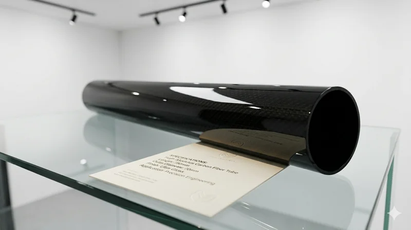
High Modulus Round Carbon Fiber Tube — M40
High modulus round tube manufactured with M40 grade fiber (tensile modulus 400 GPa). Designed for applications where maximum stiffness-to-weight ratio is critical, such as optical systems, precision machinery, and aerospace structures.

Carbon fiber standard plate-3k stripe
Lightweight, ultra-rigid standard sheets for drone fuselages, robot housings, facades and structural applications.

Square Carbon Fiber Tube — 3K Twill T700
Square cross-section carbon fiber tube manufactured with 3K twill weave for torsional strength. Preferred for structural frames, trusses, and support columns where rectangular geometry offers design flexibility.

Carbon Fiber Plate — 3K Twill T700 3.0mm
Medium-thickness 3.0mm carbon fiber plate offering significantly higher load capacity while maintaining attractive 3K twill finish. Suitable for structural brackets, reinforcement plates, and load-bearing panels.

Carbon Fiber Plate — 3K Twill T700 1.5mm
Thin 1.5mm carbon fiber plate with 3K twill weave surface. Lightweight and stiff, commonly used for covers, panels, drone bodies, and applications requiring a premium aesthetic appearance.