
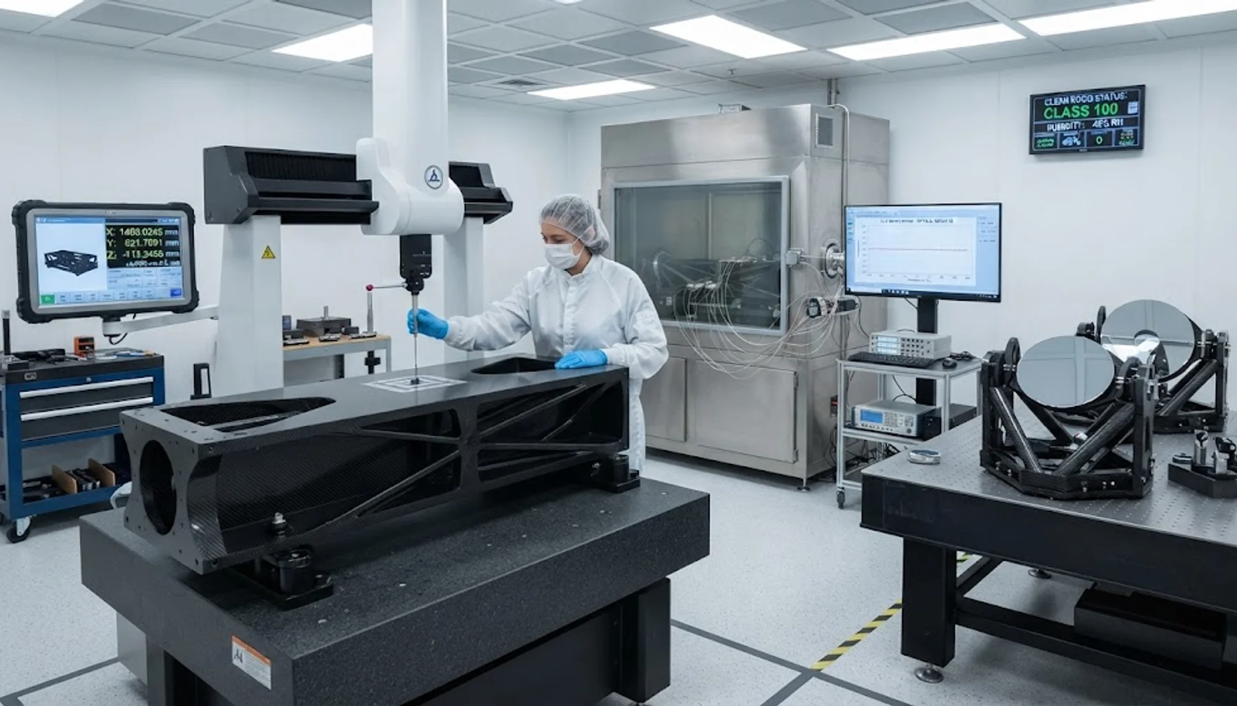
Carbon fiber optical benches achieve near-zero coefficient of thermal expansion (CTE) through quasi-isotropic layup of high-modulus carbon fiber.
Introduction
Carbon fiber optical bench systems represent one of the most demanding applications of advanced composite materials, requiring dimensional stability at the nanometer level over temperature ranges spanning -150°C to +200°C. For space telescopes, satellite instruments, and ground-based astronomical systems, the optical bench — the structural platform that holds mirrors, lenses, detectors, and other optical components in precise alignment — must maintain its geometry with extraordinary precision. Even sub-micron dimensional changes can degrade image quality, misalign optical paths, and compromise mission performance.
Carbon fiber composites, when properly designed and manufactured, achieve near-zero coefficient of thermal expansion (CTE) through quasi-isotropic layup of high-modulus fibers. This unique capability — combined with high specific stiffness, low density, and excellent vibration damping — makes carbon fiber the material of choice for optical bench structures in space and ground-based applications.
The CTE Challenge
Dimensional stability is the paramount requirement for optical bench structures. The CTE of common materials illustrates the challenge:
• Aluminum: 23 × 10⁻⁶/°C — a 1-meter aluminum structure changes length by 23 μm per degree Celsius.
• Steel: 12 × 10⁻⁶/°C — better than aluminum, but still too high for precision optics.
• Invar 36: 1.2 × 10⁻⁶/°C — a nickel-iron alloy specifically designed for low CTE, but dense (8.1 g/cm³) and difficult to machine.
• Ultra-low-expansion glass (ULE): ~0 × 10⁻⁶/°C — excellent CTE, but brittle, heavy, and limited in structural complexity.
• Carbon fiber composite (quasi-isotropic): ±0.5 × 10⁻⁶/°C — achieves near-zero CTE while providing high specific stiffness (150+ GPa/(g/cm³)) and the ability to form complex structural shapes.
CTE Tuning Through Layup Design
The CTE of a carbon fiber laminate depends on three primary variables: fiber orientation, fiber volume fraction, and cure cycle. By carefully controlling these variables, CTE can be engineered to specific values — including exactly zero — along one or more axes.
Unidirectional layup: A single ply of high-modulus carbon fiber has a negative CTE along the fiber direction (-1.0 to -1.5 × 10⁻⁶/°C) and a positive CTE in the transverse direction (+25 to +30 × 10⁻⁶/°C). By selecting the fiber volume fraction, the longitudinal CTE can be tuned to exactly zero — typically at 55–60% fiber volume fraction for high-modulus carbon.
Quasi-isotropic layup: A [0/±60/90]s or [0/±45/90]s layup sequence creates approximately equal stiffness in all in-plane directions. When using high-modulus carbon fiber (modulus > 400 GPa), quasi-isotropic layup achieves near-zero CTE in all in-plane directions — typically ±0.3 to ±0.5 × 10⁻⁶/°C.
Negative CTE layup: For applications requiring active CTE compensation (matching the CTE of a specific optical component), layups with more 0° plies than 90° plies can achieve net negative CTE values, enabling thermal shrinkage that compensates for positive-CTE components.
Space Telescope Applications
Carbon fiber optical benches are critical structural elements in major space telescope programs:
James Webb Space Telescope (JWST): The JWST uses carbon fiber reinforced polymer (CFRP) optical bench structures for its primary mirror support and instrument module. The optical bench must maintain mirror alignment to within 100 nanometers over the telescope's operating temperature range of -233°C to +120°C. The quasi-isotropic CFRP layup achieves CTE < 0.1 × 10⁻⁶/°C in the critical mirror mounting areas.
ESA Euclid mission: The Euclid visible and near-infrared instruments are mounted on a carbon fiber optical bench that provides dimensional stability for the 1.2-meter focal plane array. The bench is manufactured from M55J high-modulus carbon fiber with quasi-isotropic layup, achieving CTE < 0.2 × 10⁻⁶/°C over the operating range.
Hubble Space Telescope successor studies: Next-generation space telescope concepts (LUVOIR, HabEx) specify carbon fiber optical benches with CTE requirements below 0.05 × 10⁻⁶/°C — pushing the boundaries of current layup and manufacturing technology.
Ground-Based Astronomical Systems
Ground-based telescopes and interferometers face different thermal challenges than space systems:
Day-night thermal cycling: Ground-based observatories experience temperature variations of 10–30°C over 24-hour periods. Carbon fiber trusses and optical benches minimize thermal drift that would otherwise require constant re-alignment of optical components.
Large-baseline interferometry: Optical interferometers like the VLTI (Very Large Telescope Interferometer) use carbon fiber baseline structures spanning 10–100+ meters. The near-zero CTE of carbon fiber composites maintains baseline length stability to within nanometers over kilometer-scale distances.
Adaptive optics structures: Carbon fiber is used for mirror support structures in adaptive optics systems, where dimensional stability is critical for maintaining the nanometer-level surface accuracy required for atmospheric turbulence correction.
Manufacturing and Quality Control
Optical bench structures require exceptional manufacturing quality:
Fiber placement: Automated fiber placement (AFP) or automated tape laying (ATL) ensures precise fiber orientation — typically within ±0.5° of the designed orientation. Orientation errors directly translate to CTE errors: a 1° orientation error in a quasi-isotropic layup can shift CTE by 0.1–0.2 × 10⁻⁶/°C.
Cure cycle control: The cure cycle must be precisely controlled to achieve the designed fiber volume fraction and residual stress state. Autoclave cure at 120–180°C with ±2°C temperature uniformity is standard for high-precision optical bench structures.
Dimensional verification: Finished optical benches are measured using coordinate measuring machines (CMM) with accuracy better than 1 μm. CTE is verified by measuring dimensional changes over temperature in a thermal chamber, typically from -60°C to +80°C.
Thermal cycling: Qualification testing includes 100+ thermal cycles to verify that CTE remains stable and no dimensional drift occurs due to residual stress relaxation.
Challenges and Future Developments
Despite its excellent properties, carbon fiber for optical bench applications faces several challenges:
Moisture absorption: Carbon fiber composites absorb 0.5–1.5% moisture by weight, causing dimensional changes of 100–500 ppm. For space applications, outgassing and moisture desorption in vacuum can cause progressive dimensional drift. Mitigation strategies include moisture conditioning before assembly and selection of low-absorption resin systems.
Outgassing: Resin systems must meet NASA outgassing requirements (ASTM E595: TML < 1.0%, CVCM < 0.1%) to prevent contamination of optical surfaces in space. Cyanate ester and specialized epoxy resins are preferred for their low outgassing characteristics.
Long-term stability: Over multi-decade mission lifetimes, resin aging and radiation exposure can alter CTE and mechanical properties. Accelerated aging tests and radiation qualification are required for long-duration space missions.
Conclusion
Carbon fiber optical bench systems represent the state of the art in dimensional stability for precision structures. Through careful layup design, high-modulus fiber selection, and precision manufacturing, carbon fiber composites achieve near-zero CTE values that enable nanometer-level alignment of optical components in space telescopes, satellite instruments, and ground-based astronomical systems. As next-generation telescopes demand even tighter dimensional tolerances, carbon fiber technology will continue to advance — pushing the boundaries of what is achievable in precision composite structures.
Part of topic
Related Articles
- Carbon Fiber Mooring for Floating Offshore Wind: Fatigue and Corrosion in Deep Water
- Carbon Fiber Bicycle Frame Optimization: Layup Design and Manufacturing for Competitive Racing
- Carbon Fiber CFRP Retrofit for Infrastructure: Bridge and Building Seismic Strengthening
- Carbon Fiber Medical Imaging Equipment: Lightweight Gantry and Couch Structures for MRI/CT
- Carbon Fiber EV Battery Enclosures: Crash Safety and Electromagnetic Shielding Design
- Carbon Fiber Structures for Low-Altitude Economy: UAV Airframes and eVTOL Components
Interested in Our Products?
Contact our team for competitive pricing and technical specifications.
Get a QuoteRelated Products

Carbon Fiber Plate — 3K Twill T700 3.0mm
Medium-thickness 3.0mm carbon fiber plate offering significantly higher load capacity while maintaining attractive 3K twill finish. Suitable for structural brackets, reinforcement plates, and load-bearing panels.

Carbon Fiber Plate — 3K Twill T700 1.5mm
Thin 1.5mm carbon fiber plate with 3K twill weave surface. Lightweight and stiff, commonly used for covers, panels, drone bodies, and applications requiring a premium aesthetic appearance.

Square Carbon Fiber Tube — 3K Twill T700
Square cross-section carbon fiber tube manufactured with 3K twill weave for torsional strength. Preferred for structural frames, trusses, and support columns where rectangular geometry offers design flexibility.

Carbon Fiber Plate — UD Unidirectional T700
Unidirectional carbon fiber plate with all fibers oriented in a single direction for maximum strength along the fiber axis. Essential for structural reinforcements, splints, and applications where load direction is predictable.

Round Carbon Fiber Tube — UD Unidirectional T700
Unidirectional (UD) round tube with all fibers aligned axially for maximum longitudinal stiffness. Ideal for applications requiring high bending rigidity with minimal weight, such as shafts, struts, and structural reinforcements.