
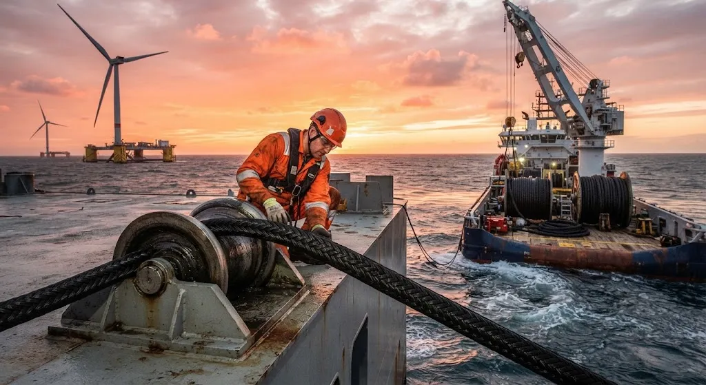
Floating offshore wind energy is expanding into deeper waters where fixed-bottom turbine foundations become technically and economically impractical. Current fixed-bottom installations are limited to approximately 60 meters water depth, while floating platforms can operate at 200-1,500 meters, openi
Introduction
Floating offshore wind energy is expanding into deeper waters where fixed-bottom turbine foundations become technically and economically impractical. Current fixed-bottom installations are limited to approximately 60 meters water depth, while floating platforms can operate at 200-1,500 meters, opening access to the 80% of global offshore wind resource located in waters deeper than 60 meters. However, as water depth increases, mooring system weight becomes the dominant design constraint. A conventional steel catenary mooring system for a 15 MW floating turbine at 1,000 meters depth weighs approximately 3,000-5,000 tons, requiring anchor holding capacities and installation vessel capabilities that push the limits of current offshore engineering.
Carbon fiber mooring lines offer a transformative solution by providing equivalent tensile strength at approximately 15-20% the weight of steel. This weight reduction directly reduces anchor loads, enables smaller installation vessels, and extends the practical depth range for floating wind platforms. For deep-water floating wind projects planned for the North Sea, Celtic Sea, and Pacific waters off Japan and the US West Coast, carbon fiber mooring technology could be the enabling factor that unlocks gigawatt-scale floating wind deployment beyond current cost and depth limitations.
Carbon Fiber Rope Construction for Mooring Applications
Carbon fiber mooring ropes differ fundamentally from conventional steel wire or chain systems in both material properties and construction methodology. The high specific strength of carbon fiber (tensile strength divided by density) enables mooring line designs that maintain the required holding capacity while dramatically reducing suspended weight in the water column.
| Property | Steel Wire Rope | Polyester Rope | Carbon Fiber Rope | Improvement vs Steel |
|---|---|---|---|---|
| Tensile strength | 1,770 MPa | 100-150 MPa | 2,500-4,000 MPa | 1.4-2.3x |
| Density | 7,850 kg/m3 | 1,380 kg/m3 | 1,600 kg/m3 | 0.20x (80% lighter) |
| Specific strength | 225 kNm/kg | 109 kNm/kg | 1,560-2,500 kNm/kg | 7-11x |
| Wet weight per unit length | Baseline | 0.25x steel | 0.22x steel | 78% weight reduction |
| Corrosion resistance | Requires coating | Inherent | Inherent | No maintenance |
| Stiffness (axial) | High (160 GPa) | Low (2-4 GPa) | Medium-High (80-150 GPa) | Adjustable |
The construction of carbon fiber mooring ropes typically follows a multi-layer braided or parallel strand architecture. The inner core consists of parallel unidirectional carbon fiber bundles, each containing 12,000-50,000 filaments, bonded with a thermoset or thermoplastic resin matrix. Outer layers use braided carbon fiber or hybrid carbon-aramid sheaths that provide abrasion resistance and distribute lateral loads across the core. The braided sheath pattern is specifically designed to accommodate the low elongation of carbon fiber (1.5-2.5% at breaking load) while preventing fiber buckling under compressive loading near the touchdown zone on the seabed.
Fatigue Performance Under Cyclic Ocean Loading
Fatigue resistance is arguably the most critical performance metric for carbon fiber mooring lines, since these components must endure 20-30 years of continuous cyclic loading from wind, wave, and current forces. Unlike steel wire rope, which exhibits well-characterized S-N curves based on decades of offshore data, carbon fiber rope fatigue behavior requires specialized testing methodologies and extrapolation approaches.
The fatigue loading spectrum for a floating wind turbine mooring line combines multiple frequency components: high-frequency turbine vibration (1-3 Hz), wave-frequency orbital motion (0.05-0.15 Hz), and low-frequency platform drift (0.001-0.01 Hz). This broadband loading creates complex stress histories that differ from the constant-amplitude fatigue tests used in laboratory characterization.
- Fiber-level fatigue: Individual carbon fibers demonstrate excellent fatigue resistance, retaining 90-95% of initial strength after 10 million cycles at 60% of ultimate tensile strength. This performance exceeds steel wire at equivalent stress ratios.
- Matrix-dominated fatigue: The resin matrix and fiber-matrix interface are the limiting factors in rope fatigue life. Cyclic loading creates micro-cracking in the resin, which gradually reduces load transfer efficiency between fibers. Thermoplastic matrix systems show superior fatigue performance compared to thermoset systems due to their ability to arrest crack propagation through local yielding.
- Creep behavior: Under sustained loading, carbon fiber ropes exhibit minimal creep (less than 0.1% strain over 10,000 hours at 40% of breaking load), significantly outperforming polyester ropes which may creep 2-5% under equivalent conditions. This dimensional stability is critical for maintaining platform station-keeping requirements.
Full-scale fatigue testing programs at institutions such as MARIN (Netherlands) and the University of Western Australia have demonstrated that properly designed carbon fiber mooring ropes can exceed 2 million load cycles at 50% of breaking load without significant strength degradation. Extrapolation to field conditions suggests service lives of 20-25 years are achievable with appropriate safety factors and inspection regimes.
Corrosion Resistance in Marine Environments
One of the most compelling advantages of carbon fiber mooring lines over steel systems is their inherent resistance to seawater corrosion. Steel wire rope in marine environments suffers from pitting corrosion, crevice corrosion, and hydrogen embrittlement, requiring sacrificial anodes, protective coatings, and regular inspection programs. These corrosion mitigation measures add 15-25% to the lifetime cost of steel mooring systems.
Carbon fiber itself is electrochemically inert in seawater, showing no measurable corrosion rate in immersion tests lasting over 5 years. However, the composite rope structure presents unique challenges at the interfaces between fibers, matrix, and any metallic end-fittings. The primary corrosion concerns in carbon fiber mooring systems include:
- End-fitting galvanic corrosion: When carbon fiber contacts stainless steel fittings in seawater, galvanic corrosion of the steel can occur. Solutions include isolation sleeves, titanium fittings (which are galvanically compatible with carbon fiber), or composite-to-composite connection systems that eliminate metallic components entirely.
- Matrix hydrolysis: Some thermoset resin systems absorb 1-3% moisture by weight over extended immersion, which can degrade fiber-matrix bond strength by 10-20%. Thermoplastic matrices (PEEK, PA) and highly cross-linked epoxy systems demonstrate superior hydrolysis resistance.
- Fiber surface degradation: UV exposure during surface storage periods can degrade the fiber sizing treatment, reducing subsequent load transfer efficiency. Protective coatings and proper storage protocols mitigate this risk during the installation phase.
Long-term immersion studies conducted in the North Sea and tropical Pacific waters show that carbon fiber composite ropes retain 85-95% of their original breaking strength after 5 years of continuous submersion, compared to 70-80% for galvanized steel wire rope without active cathodic protection.
Economic Analysis and Commercial Viability
The business case for carbon fiber mooring lines depends on the interplay between material cost premium, installation cost savings, and operational expenditure reductions over the 25-30 year project lifetime. Current carbon fiber rope costs are approximately 3-5 times higher per meter than equivalent steel wire rope, but the total installed cost comparison tells a different story.
For a typical 15 MW floating wind turbine at 800 meters water depth with 3-point catenary mooring, the installed cost comparison shows carbon fiber systems can be cost-competitive when water depth exceeds approximately 600-800 meters. The key cost drivers favoring carbon fiber include smaller anchor foundations (50-70% less holding capacity required), reduced installation vessel requirements (smaller crane capacity, shorter installation time), and elimination of ongoing corrosion maintenance costs. For ultra-deep installations beyond 1,200 meters, carbon fiber mooring becomes the only technically feasible option, as steel systems become impractical due to self-weight limitations.
Frequently Asked Questions
What is the maximum water depth where carbon fiber mooring is technically viable?
Carbon fiber mooring lines have been analyzed for water depths up to 3,000 meters in academic studies and concept designs. At these extreme depths, the weight advantage of carbon fiber becomes overwhelming — a steel mooring system at 3,000 meters would be so heavy that the suspended weight alone exceeds the mooring restoring force capacity. Carbon fiber mooring lines maintain adequate restoring force at these depths because their low weight-to-strength ratio means the catenary profile is dominated by horizontal tension rather than vertical weight. Current commercial deployment targets are 1,000-2,000 meters, with first-of-kind installations expected before 2030.
How do carbon fiber mooring lines handle extreme storm events?
Carbon fiber mooring ropes are designed with safety factors of 2.0-2.5 against breaking load for extreme storm conditions (typically the 100-year return period environmental loading). During extreme events, the rope experiences peak tensions of 40-60% of breaking load, well within the fatigue envelope. The low elongation of carbon fiber (1.5-2.5% at break) means platform excursions are smaller than with steel or polyester systems, which can be advantageous for maintaining turbine operability during storms. However, the low elongation also means less energy absorption per cycle, requiring careful system design to avoid snap loading during rapid wind speed changes.
What inspection and maintenance is required for carbon fiber mooring systems?
Carbon fiber mooring systems require significantly less maintenance than steel alternatives. Recommended inspection intervals are 5-7 years for routine underwater ROV surveys (compared to 2-3 years for steel systems), focusing on end-fitting integrity, rope surface condition, and any signs of fiber damage from seabed interaction. The absence of corrosion eliminates the need for cathodic protection system monitoring and anode replacement. Operational monitoring through onboard tension sensors provides continuous assessment of mooring line condition, enabling condition-based maintenance rather than time-based replacement. Estimated lifecycle maintenance cost is 30-50% lower than equivalent steel systems.
Conclusion
Carbon fiber mooring lines represent a step-change in deep-water floating wind platform design, addressing the fundamental weight limitation that constrains conventional steel mooring systems beyond 600-800 meters water depth. The combination of 80% weight reduction, inherent corrosion resistance, excellent fatigue performance, and lifecycle cost advantages positions carbon fiber as the enabling technology for the next generation of floating wind farms in ultra-deep waters. As production volumes increase and manufacturing processes mature, the cost premium over steel will continue to narrow, expanding the depth range where carbon fiber mooring delivers clear economic benefits.
For project developers and marine engineers evaluating mooring system options for floating wind installations, explore our offshore-grade carbon fiber materials, or contact our technical team to discuss how carbon fiber mooring solutions can support your deep-water floating wind project requirements.
Related Articles
- Carbon Fiber Bicycle Frame Optimization: Layup Design and Manufacturing for Competitive Racing
- Carbon Fiber CFRP Retrofit for Infrastructure: Bridge and Building Seismic Strengthening
- Carbon Fiber Medical Imaging Equipment: Lightweight Gantry and Couch Structures for MRI/CT
- Carbon Fiber EV Battery Enclosures: Crash Safety and Electromagnetic Shielding Design
- Carbon Fiber Structures for Low-Altitude Economy: UAV Airframes and eVTOL Components
- Carbon Fiber Satellite Structures: Dimensional Stability for Space Environment Cycling
Interested in Our Products?
Contact our team for competitive pricing and technical specifications.
Get a QuoteRelated Products

Carbon Fiber Plate — 3K Twill T700 1.5mm
Thin 1.5mm carbon fiber plate with 3K twill weave surface. Lightweight and stiff, commonly used for covers, panels, drone bodies, and applications requiring a premium aesthetic appearance.

Carbon Fiber Plate — 3K Twill T700 3.0mm
Medium-thickness 3.0mm carbon fiber plate offering significantly higher load capacity while maintaining attractive 3K twill finish. Suitable for structural brackets, reinforcement plates, and load-bearing panels.

Square Carbon Fiber Tube — 3K Twill T700
Square cross-section carbon fiber tube manufactured with 3K twill weave for torsional strength. Preferred for structural frames, trusses, and support columns where rectangular geometry offers design flexibility.

Carbon Fiber Plate — UD Unidirectional T700
Unidirectional carbon fiber plate with all fibers oriented in a single direction for maximum strength along the fiber axis. Essential for structural reinforcements, splints, and applications where load direction is predictable.

Round Carbon Fiber Tube — UD Unidirectional T700
Unidirectional (UD) round tube with all fibers aligned axially for maximum longitudinal stiffness. Ideal for applications requiring high bending rigidity with minimal weight, such as shafts, struts, and structural reinforcements.