
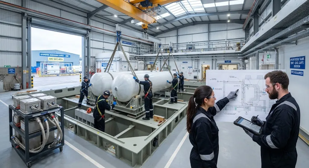
Hydrogen propulsion on the water sounds like a distant ambition until the economics of short-sea routes are laid out on paper. A ferry that crosses a fjord or runs a commuter route of 30-60 minutes needs a limited energy buffer, can refuel at a fixed terminal, and returns to the same be
Introduction
Hydrogen propulsion on the water sounds like a distant ambition until the economics of short-sea routes are laid out on paper. A ferry that crosses a fjord or runs a commuter route of 30-60 minutes needs a limited energy buffer, can refuel at a fixed terminal, and returns to the same berth every day. Those three facts make it the natural first customer for fuel-cell drivetrains, and they explain why most of the marine hydrogen projects announced over the past three years are ferries, crew transfer vessels and port service craft rather than ocean-going ships. The battery-electric ferries that came first proved the operating model; hydrogen exists to extend the range where batteries run out of mass budget.
The storage system is the decisive engineering constraint in that extension. A Type IV pressure vessel — a carbon fiber composite overwrap over a polymer liner — is the standard hardware now specified in nearly every declared hydrogen ferry design, from the Norwegian MF Hydra of 2021 to the U.S. SEA Change and the Swedish Topeka project. This article covers the on-board integration of Type IV tanks, the ventilation and gas-detection rules that marine classification societies apply to them, the port-side storage systems that make bunkering reliable, and a comparison with the alternative hydrogen carriers that compete for the same route economics.
Why Type IV Tanks Fit Short-Sea Profiles
The reason Type IV tanks dominate marine hydrogen designs is a weight story told in numbers. A compressed-hydrogen system stores gas in the volume of the tank shell, and the shell must carry its own pressure without contributing useful payload. Composite overwrap tanks reach a system gravimetric density of roughly 5-6 percent — five to six kilograms of hydrogen per 100 kilograms of tank — which is where the entire fuel-cell vessel math begins. The table below compares the storage options that ship designers currently trade off against each other:
| Storage option | H2 volumetric density | System weight per kg H2 | Marine maturity | Main constraint |
|---|---|---|---|---|
| Type IV compressed, 350 bar | ~24-28 kg/m3 | ~17-20 kg | Class-approved on operating ferries | Large tank volume per unit of energy |
| Type IV compressed, 700 bar | ~40 kg/m3 | ~18-22 kg | Proven on land, early marine use | Higher compressor and fueling costs |
| Liquid hydrogen (LH2) | ~70 kg/m3 | ~8-12 kg for tank, plus plant | Prototype stage on water | Boil-off, cryogenic bunkering complexity |
| Ammonia carrier | ~120 kg H2-equiv/m3 | ~5-6 kg per kg H2 too good to ignore | Engine trials, no fuel-cell fleet | Cracking energy, toxicity, NOx slip |
Compressed hydrogen loses the volumetric contest but wins on regulatory maturity and daily operating simplicity. For a ferry that sleeps a tank cascade on the upper deck or in a dedicated casing, 350 bar storage is the configuration with the most class-approval precedent, and 700 bar is being introduced where volume is tight. Liquid hydrogen offers a better long-range answer but drags cryogenic plant, boil-off management and specialized bunkering into a daily commuter operation. Ammonia, meanwhile, is attractive as an energy-dense carrier but displaces the storage problem with a fuel-handling problem of its own.
On-Board Arrangement and the Rule Framework
Classification of hydrogen-fueled vessels currently converges on the IMO IGF Code as the parent framework, with class societies — DNV, Lloyd's Register, Bureau Veritas, ClassNK — publishing supplementary hydrogen guidance that fills the gaps the code does not yet cover. The practical effect of these rules is a set of placement and protection requirements that shape every tank installation:
- Dedicated tank spaces: Type IV tanks are installed in enclosed, gas-tight compartments with controlled ventilation rates, separated from accommodation, machinery and cargo spaces by cofferdams or equivalent boundaries.
- Ventilation capacity: gas-safe ventilation of the tank space is sized to clear a full-bore leak scenario in minutes; ventilation failure typically triggers the same trip levels as gas detection, not a separate, slower alarm.
- Hydrogen gas detection: point sensors and sampling lines are arranged so that any leak in the tank casing raises an alarm at 20 percent and 40 percent of the lower flammability limit, with the higher threshold initiating fuel isolation and ventilation boost.
- Pressure relief and vent mast: each tank is fitted with thermally activated pressure relief devices that route hydrogen to a vent mast clear of ignition sources, air intakes and personnel routes.
- Fire protection and crash scenarios: tank spaces receive structural fire protection ratings, and the hull arrangement must survive defined collision and grounding damage without exposing the pressure vessels.
The consequence is that Type IV tanks on a ferry look modular from the outside but are never an add-on: the hull geometry, the deck structure and the ventilation ducting are designed around the tank space from the first concept sketch, which is why storage integration typically drives the general arrangement of a hydrogen ferry rather than the other way around.
Port-Side Storage and Bunkering Cascades
On-shore, the same Type IV technology appears in a different role. Port bunkering facilities for commuter hydrogen routes are increasingly built as cascades of Type IV tanks rather than traditional pressure vessels, because the composite overwrap ships lighter, installs faster and tolerates the cyclic filling and emptying of a bunkering buffer better than seamless steel. A typical port installation couples a cascade of 350-500 bar tanks with a compressor station, a priority-control system that sequences the cascade to minimize compressor work, and a transfer hose arrangement that returns gas from vehicle tanks before refueling. The operating loop is simple in concept: electrolyzers or delivered tube-trailers supply the cascade, the cascade feeds the ferry bunkering skid, and the ferry burns the fuel over a single day's sailings before returning to the same berth.
That closed loop is exactly why port systems are as important as the vessels themselves. If the shore side cannot deliver a full charge in the parked window between sailings, the economics of the route collapse regardless of how good the on-board tanks are. Several European port hydrogen projects are therefore treating the shore cascade, not the vessel, as the critical path item, and are standardizing Type IV cascades as the low-risk, quickly deployable backbone of the refueling station.
Frequently Asked Questions
Why are Type IV tanks preferred over steel pressure vessels for marine hydrogen?
Type IV tanks store the same mass of hydrogen in a significantly lighter pressure vessel, because the carbon fiber overwrap carries the pressure load with roughly one quarter of the steel weight. On a vessel, that weight saving converts directly into payload or fuel capacity. Type IV tanks also tolerate cyclic filling better than heavy steel vessels and ship as lighter, more compact modules that are easier to install in the restricted spaces of a ferry deck or a port bunkering station. The trade-offs are a higher unit cost and the need for a protective casing, which the marine rules require anyway.
What happens if hydrogen leaks on board a ferry?
Gas detection is arranged to catch a leak while it is still small. Sensors in the tank space alarm at 20 percent of the lower flammability limit and initiate fuel isolation and increased ventilation at 40 percent. Because hydrogen rises quickly, detectors are mounted high in the compartment and ventilation is designed to flush the space to the vent mast rather than to internal spaces. The combination of continuous ventilation, early detection and automatic isolation means the leak is removed from the flammable range before it can accumulate to an ignition concentration in normal operation.
Is liquid hydrogen a better option for ferries than compressed storage?
Liquid hydrogen stores more energy per volume and is the right answer for long-range vessels where tank volume is the binding constraint. For short-sea commuter routes, however, compressed Type IV storage is almost always the more practical choice: it avoids cryogenic plant on board, removes boil-off handling, and matches the daily bunkering cycle with well-understood 350-700 bar equipment. The industry is watching LH2 prototypes carefully, but until the port-side cryogenic infrastructure exists along the routes that need it, compressed storage remains the deployable default.
Conclusion
Marine hydrogen is being built around the Type IV tank system, and the pattern is consistent across the projects that are actually sailing: short-sea ferries, crew transfer vessels and port service craft choose 350-700 bar composite storage because it is the option with class-approval precedent, manageable weight and a shore-side ecosystem that can be stood up in months rather than years. The tank arrangement drives the hull design, the ventilation and gas detection rules drive the tank space, and the port cascade drives the daily economics — three layers that all have to work together for the route to function.
If your hydrogen vessel program needs high-pressure composite storage hardware, review our carbon fiber cylinder and tank solutions or contact our engineering team to discuss Type IV tank design, prototype winding and the test documentation that marine classification requires.
Part of topic
Related Articles
- Carbon Fiber Mooring for Floating Offshore Wind: Fatigue and Corrosion in Deep Water
- Carbon Fiber Bicycle Frame Optimization: Layup Design and Manufacturing for Competitive Racing
- Carbon Fiber CFRP Retrofit for Infrastructure: Bridge and Building Seismic Strengthening
- Carbon Fiber Medical Imaging Equipment: Lightweight Gantry and Couch Structures for MRI/CT
- Carbon Fiber EV Battery Enclosures: Crash Safety and Electromagnetic Shielding Design
- Carbon Fiber Structures for Low-Altitude Economy: UAV Airframes and eVTOL Components
Interested in Our Products?
Contact our team for competitive pricing and technical specifications.
Get a QuoteRelated Products

Carbon Fiber Plate — 3K Twill T700 1.5mm
Thin 1.5mm carbon fiber plate with 3K twill weave surface. Lightweight and stiff, commonly used for covers, panels, drone bodies, and applications requiring a premium aesthetic appearance.

Square Carbon Fiber Tube — 3K Twill T700
Square cross-section carbon fiber tube manufactured with 3K twill weave for torsional strength. Preferred for structural frames, trusses, and support columns where rectangular geometry offers design flexibility.

Carbon Fiber Plate — UD Unidirectional T700
Unidirectional carbon fiber plate with all fibers oriented in a single direction for maximum strength along the fiber axis. Essential for structural reinforcements, splints, and applications where load direction is predictable.

Round Carbon Fiber Tube — UD Unidirectional T700
Unidirectional (UD) round tube with all fibers aligned axially for maximum longitudinal stiffness. Ideal for applications requiring high bending rigidity with minimal weight, such as shafts, struts, and structural reinforcements.
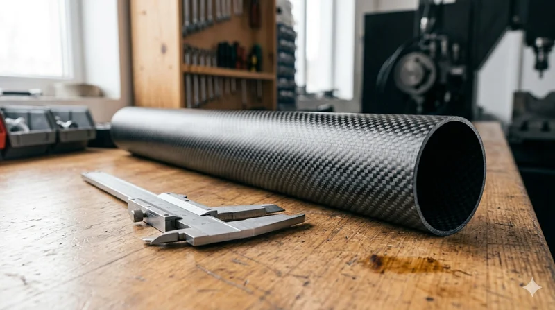
Round Carbon Fiber Tube — 3K Plain Weave T700
Standard round carbon fiber tube manufactured from Toray T700 grade fiber with 3K plain weave. Offers balanced strength and stiffness for general industrial applications including robotics, automation, sports equipment, and aerospace structures.