
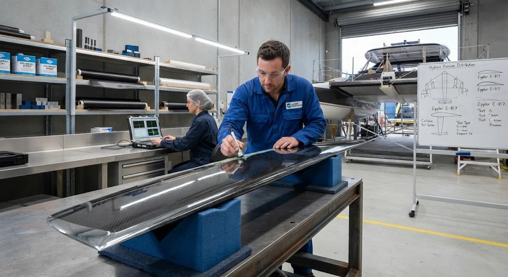
Marine hydrofoils lift a vessel's hull above the water surface at speed, reducing hydrodynamic drag by up to 80% compared to conventional displacement hulls. Carbon fiber reinforced polymer (CFRP) has become the material of choice for hydrofoil structures because it delivers the high specific stiffn
Introduction
Marine hydrofoils lift a vessel's hull above the water surface at speed, reducing hydrodynamic drag by up to 80% compared to conventional displacement hulls. Carbon fiber reinforced polymer (CFRP) has become the material of choice for hydrofoil structures because it delivers the high specific stiffness, fatigue resistance, and corrosion immunity required for these demanding marine applications. From passenger ferries in Scandinavia to racing catamarans and naval interceptors, carbon fiber hydrofoils enable vessels to achieve speeds above 40 knots while cutting fuel consumption by 30-50%.
The design of a carbon fiber marine hydrofoil structure requires balancing extreme hydrodynamic loading, impact resistance, and long-term fatigue performance in a saltwater environment. Unlike land-based composites, hydrofoils experience cyclic pressure loads from wave slamming, cavitation erosion on leading edges, and electrochemical exposure to seawater — all while operating in a weight-critical configuration where every kilogram saved translates directly into higher speed or greater payload. This article provides a comprehensive technical guide for engineers and buyers evaluating carbon fiber hydrofoil systems for commercial, defense, and recreational marine applications.
Hydrofoil Configuration and Design Principles
Hydrofoil vessels use one of three primary foil configurations, each with distinct structural requirements for carbon fiber construction:
- Surface-piercing foils (M-foil): The foil tips break the water surface as speed increases, providing automatic altitude control through reduced submerged area. Carbon fiber M-foils require a hydrophobic leading edge treatment and stiff taper sections to resist bending moments at the waterline.
- Fully submerged foils: The entire foil operates below the waterline, controlled by electronic sensors and actuators. These foils experience higher bending loads because the full span carries hydrodynamic force, demanding higher modulus carbon fiber layups with increased skin thickness at the root.
- T-foil (elevon) configurations: A single foil mounted under the bow or stern with horizontal control surfaces. T-foils concentrate structural loads in a compact root section, making carbon fiber's high specific strength particularly advantageous for weight reduction at the attachment point.
The critical design parameter for all configurations is the lift-to-drag ratio of the foil section. Carbon fiber enables thinner, more efficient foil profiles than aluminum or steel because CFRP's specific stiffness allows designers to reduce section thickness by 20-30% while maintaining the same structural deflection limits. This translates directly into lower induced drag and higher vessel speed for a given power input.
Carbon Fiber Layup and Material Selection
Hydrofoil structures operate in a unique combination of high static loads, cyclic fatigue, and environmental exposure. The layup design must address all three simultaneously:
| Design Parameter | Requirement | Typical CFRP Solution | Performance Impact |
|---|---|---|---|
| Primary bending stiffness | Resist hydrodynamic lift forces | Unidirectional T700/T800 at 0°, 55-65% fiber volume | Controls foil deflection under load |
| Torsional rigidity | Prevent pitch oscillation | ±45° biaxial glass or carbon skins | Stabilizes foil at high speed |
| Impact resistance | Survive wave slamming and debris | Hybrid carbon-aramid face sheets, foam core | Absorbs energy without catastrophic failure |
| Cavitation erosion | Leading edge durability | Tungsten carbide-filled epoxy coating, sacrificial strip | Extends foil life 3-5x in cavitating flow |
| Saltwater resistance | No galvanic corrosion | Full CFRP laminate, gelcoat or polyurethane topcoat | Zero corrosion vs. aluminum or steel |
| Fatigue life | 10⁸-10⁹ cycles minimum | Toughened resin system, balanced symmetric layup | Ensures 20+ year service life |
The skin-to-core bond is a critical failure point in sandwich construction hydrofoils. Balsa core is commonly used for its superior shear strength, but closed-cell PVC or PMI foam cores offer better moisture resistance in permanently submerged applications. The core thickness is typically 15-25 mm, increasing toward the root to handle rising shear loads. Vacuum infusion or prepreg autoclave curing are the two dominant manufacturing routes, with prepreg offering tighter void content control (below 1%) at higher material cost.
Structural Analysis and Load Cases
Hydrofoil structural analysis requires modeling multiple simultaneous load cases that differ fundamentally from conventional hull structures:
- Steady-state lift: The foil generates lift proportional to speed squared. At 40 knots, a 2-meter chord hydrofoil experiences upward forces of 50-150 kN depending on vessel displacement and foil area.
- Wave impact (slamming): When the foil re-enters the water after a wave, transient impact pressures can reach 500-2000 kPa — 5-20 times the steady-state load. This is the governing load case for most hydrofoil structural designs.
- Cavitation collapse: Cavitation bubbles collapse near the foil surface, generating localized pressure spikes of up to 1 GPa. While primarily a surface erosion phenomenon, repeated cavitation events cause fatigue microcracking in the outer laminate plies.
- Maneuver loads: Turning generates asymmetric loading across the foil span, with root bending moments increasing by 40-60% compared to straight-line operation.
Finite element analysis (FEA) combined with computational fluid dynamics (CFD) is now standard practice for hydrofoil design. The FEA model must capture the fluid-structure interaction to predict dynamic deflection under time-varying pressure fields, and the composite layup must be optimized using classical lamination theory (CLT) to ensure first-ply failure margins exceed 2.0 for all critical load cases.
Frequently Asked Questions
How much weight can carbon fiber save compared to aluminum hydrofoils?
Carbon fiber hydrofoils typically weigh 40-60% less than equivalent aluminum foils for the same stiffness and strength requirements. A 3-meter aluminum hydrofoil might weigh 80-120 kg, while a carbon fiber equivalent weighs 35-55 kg. For a passenger ferry carrying four foils, this 180-260 kg weight reduction translates directly into 1-2% lower fuel consumption at cruise speed, or equivalently, the ability to carry 2-4 additional passengers at the same power setting. Over a 20-year service life with thousands of operating hours, the cumulative fuel savings significantly exceed the higher initial material cost of carbon fiber.
What maintenance do carbon fiber hydrofoils require compared to metal foils?
Carbon fiber hydrofoils require significantly less maintenance than aluminum or steel foils because CFRP is immune to galvanic corrosion in seawater. Aluminum foils need sacrificial zinc anode replacement every 6-12 months and periodic repainting to prevent pitting corrosion. Carbon fiber foils require only annual visual inspection for leading edge erosion, periodic coating touch-up at cavitation zones, and bond-line inspection every 3-5 years using tap testing or thermography. The main maintenance concern for carbon fiber is impact damage from floating debris, which requires prompt repair to prevent moisture ingress into the laminate core.
Can carbon fiber hydrofoils be repaired in the field?
Yes, carbon fiber hydrofoils can be repaired in the field using wet layup or pre-impregnated patch techniques, though the repair quality depends on the damage extent and available facilities. Small leading edge chips and surface erosion can be repaired with epoxy filler and fairing compound during routine dry-dock periods. Larger damage requiring structural laminate repair should be performed in a controlled environment with proper vacuum bagging and heat application to ensure adequate cure and bond strength. For fleet operators, carrying pre-cut carbon fiber repair kits and trained composite technicians can minimize vessel downtime. The repair process is comparable in complexity to aircraft composite repair procedures, following similar quality assurance standards.
Conclusion
Carbon fiber marine hydrofoil structures represent the optimal balance of speed, efficiency, and durability for high-performance marine vessels. The material's specific stiffness enables thinner, more hydrodynamically efficient foil profiles, while its corrosion immunity eliminates the maintenance burden associated with metal foils in saltwater environments. As hydrofoil technology expands from niche racing and ferry applications into autonomous vessels and urban air mobility boats, carbon fiber will remain the enabling material for these next-generation marine platforms.
For naval architects and marine engineers evaluating hydrofoil material options, the critical decision factors are total lifecycle cost, weight budget, and environmental durability. Explore our carbon fiber marine structural solutions or contact our engineering team to discuss material selection and layup optimization for your hydrofoil program.
Related Articles
- Carbon Fiber Deployable Structures for Satellites: Boom and Antenna Mast Applications
- Carbon Fiber Electromagnetic Interference Shielding: EMI Solutions for Electronics and 5G
- Carbon Fiber Drone Propeller Blades: Lightweight Design for Endurance and Payload
- Carbon Fiber Reusable Launch Vehicle Structures: Thermal Protection and Structural Integrity
- Carbon Fiber Underwater Robots and AUVs: Hydrostatic Pressure and Corrosion Resistance
- Carbon Fiber Electric Aircraft Propulsion: Lightweight Motor Housings and Nacelle Structures
Interested in Our Products?
Contact our team for competitive pricing and technical specifications.
Get a QuoteRelated Products

Carbon Fiber Plate — 3K Twill T700 1.5mm
Thin 1.5mm carbon fiber plate with 3K twill weave surface. Lightweight and stiff, commonly used for covers, panels, drone bodies, and applications requiring a premium aesthetic appearance.

Carbon Fiber Plate — 3K Twill T700 3.0mm
Medium-thickness 3.0mm carbon fiber plate offering significantly higher load capacity while maintaining attractive 3K twill finish. Suitable for structural brackets, reinforcement plates, and load-bearing panels.

Square Carbon Fiber Tube — 3K Twill T700
Square cross-section carbon fiber tube manufactured with 3K twill weave for torsional strength. Preferred for structural frames, trusses, and support columns where rectangular geometry offers design flexibility.

Carbon Fiber Plate — UD Unidirectional T700
Unidirectional carbon fiber plate with all fibers oriented in a single direction for maximum strength along the fiber axis. Essential for structural reinforcements, splints, and applications where load direction is predictable.

Round Carbon Fiber Tube — UD Unidirectional T700
Unidirectional (UD) round tube with all fibers aligned axially for maximum longitudinal stiffness. Ideal for applications requiring high bending rigidity with minimal weight, such as shafts, struts, and structural reinforcements.