
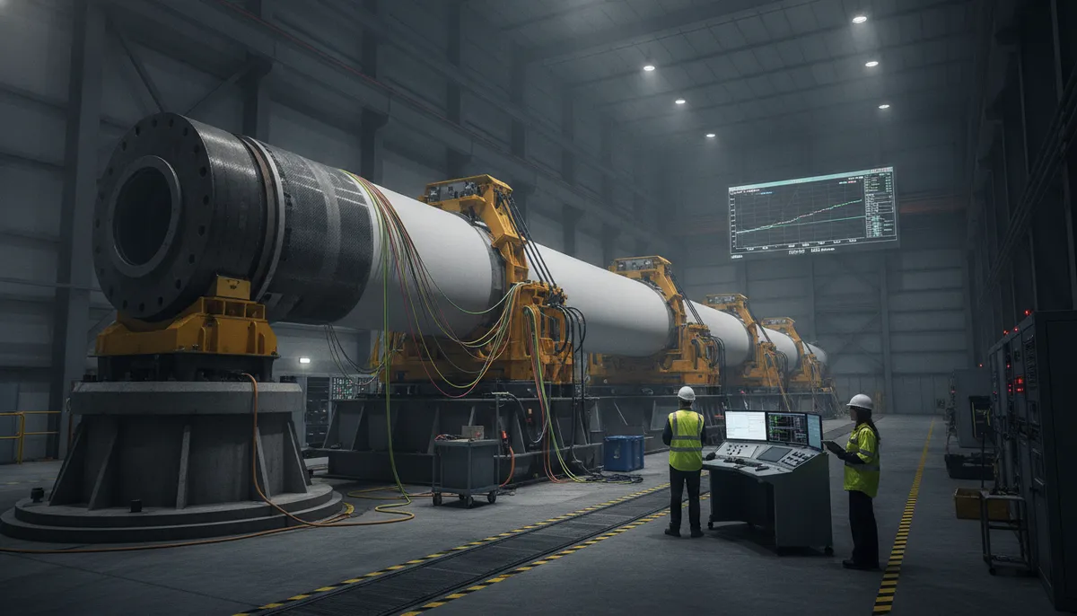
No wind turbine blade reaches the field on the strength of analysis alone. Even the most detailed finite element model must be confronted with reality at full scale: a blade the size of a civil aircraft wing, loaded until it bends, cracks, and in one sacrificial test, breaks. Full-scale
Introduction
No wind turbine blade reaches the field on the strength of analysis alone. Even the most detailed finite element model must be confronted with reality at full scale: a blade the size of a civil aircraft wing, loaded until it bends, cracks, and in one sacrificial test, breaks. Full-scale blade testing exists because the consequences of an in-service blade failure are catastrophic — a released blade section can destroy nacelle, tower, and neighboring turbines, and the certification authorities therefore require physical proof that every blade model can survive both extreme loads and the accumulated fatigue of twenty years of operation.
The testing regime is defined by IEC 61400-23, the international standard for full-scale structural testing of wind turbine blades. It covers three pillars: static tests that demonstrate ultimate strength margins, fatigue tests that reproduce decades of load cycles in months, and the component and material tests that feed the model validation chain. This article walks through each pillar, explains how a blade passes from test rig to type certificate, and uses the recent Gurit 98-meter blade — which passed five million fatigue cycles under IEC 61400-23 validation — as a benchmark for what modern testing demands.
Why Full-Scale Testing Is Unavoidable
Blade certification is anchored in physical evidence because scale effects and manufacturing variability cannot be captured by coupon testing alone. A root region laminate may behave perfectly in a lab coupon yet fail in the full blade because of local geometry, ply drop-offs, or bond-line defects that only manifest at full size. The practical drivers are consistent:
- Ultimate load validation: the blade must demonstrate that it withstands the extreme loads from the design load case envelope — typically the 50-year recurrence gust — with defined safety factors, without collapsing.
- Fatigue life proof: twenty years of operation corresponds to several hundred million load cycles at the root, and the standard accepts accelerated testing down to roughly five million representative cycles that damage the structure equivalently.
- Model calibration: strain, deflection, and natural frequency measurements from full-scale tests validate the finite element model, which then becomes the certified basis for the blade design.
- Manufacturing quality confirmation: each blade produced carries the same design, but testing proves that the manufacturing process — layup, infusion, curing, and bonding — consistently delivers the design strength.
Without full-scale evidence, no independent certification body will issue the type certificate that turbine OEMs, project lenders, and insurers all require before a blade design can be serial-produced and sold.
The Static Test: Proving Ultimate Strength
The static test loads the blade to its design ultimate load in one direction at a time. The blade is mounted root-down in a steel test stand, loaded through a system of saddles and hydraulic actuators, and instrumented with hundreds of strain gauges, string potentiometers, and digital image correlation cameras. The objective is not to break the blade — it is to demonstrate that deflections, strains, and stiffness match the validated model and that no damage occurs at the design ultimate load. Typical loading is defined as a percentage of the ultimate load:
| Test Load Level | % of Design Ultimate Load | Validation Purpose |
|---|---|---|
| Service load level (SLS) | 60-70% | Check deflection and strain against model, confirm no visible damage |
| Ultimate load level (ULS) | 100% | Hold for 10-60 seconds, demonstrate strength with defined margin |
| Ultimate load with safety factor | 100-120% | Optional demonstration of margin beyond the certified load |
| Failure test | Beyond ULS | One sacrificial blade, load until collapse to identify the failure mechanism |
The blade must hold the ultimate load without catastrophic failure, global buckling, or significant stiffness degradation, and measured strains must stay within the band predicted by the calibrated model. For 98-meter-class blades the tip deflects tens of meters while root bending moment approaches the design limit; one blade per batch of two or three is typically dedicated to this static ultimate test.
The Fatigue Test: Five Million Cycles and Beyond
Fatigue testing compresses twenty years of load history into months by cycling the blade at resonance. The blade is mounted cantilevered in the test stand and driven at its own natural frequency by an actuator, either a rotating eccentric-mass exciter or a hydraulic shaker, so that each cycle stores and releases the same elastic energy. The load spectrum is block-loaded to approximate the damage of the real wind spectrum, and the blade is rotated or repositioned between blocks so that both the flapwise and edgewise directions are exercised. The table below summarizes standard fatigue test parameters for a modern offshore-class blade:
| Parameter | Typical Value (Modern Offshore Blade) | Note |
|---|---|---|
| Target cycles (fatigue life equivalence) | ~5,000,000 | Equivalent damage to 20-year life spectrum |
| Test frequency | 0.5-1.5 Hz | Resonance-driven, near first natural frequency |
| Test duration | 6-10 months | Continuous cycling, often 24/7 |
| Strain monitoring | Continuous | Gauge drift tracking damage accumulation |
| Pass criterion | No failure, stiffness loss within limit | Residual strength checked on spare blade |
The recent Gurit case illustrates the standard in action: a 98-meter blade completed five million fatigue cycles validated under IEC 61400-23 against root delamination complaints from earlier field service — the accelerated test reproduced the exact trailing-edge and root load cases that had caused disbonding in service, and the redesigned root laminate survived the full program. For carbon fiber spar caps — increasingly common in long blades to reduce mass — fatigue testing is especially demanding because carbon is notch-sensitive and shows no plastic warning before failure, so strain monitoring must resolve small stiffness changes that precede carbon fiber failure.
IEC 61400-23 and the Certification Chain
IEC 61400-23 defines both the testing procedures and the acceptance criteria, and it is the reference standard adopted by certification bodies such as DNV and TÜV. The standard requires that full-scale testing be complemented by a complete validation chain, which the test plan must document:
- Material data: coupon-level static and fatigue properties of every laminate, gel coat, adhesive, and core used in the blade.
- Subcomponent tests: bond-line, web-to-skin, and trailing-edge samples tested to verify design details before the full blade is committed to the rig.
- Full-scale static test: ultimate load demonstration with strain and deflection correlation to the model.
- Full-scale fatigue test: accelerated cyclic loading with continuous damage monitoring and defined inspection intervals.
- Residual strength and inspection: after fatigue, a spare blade or a section is tested to confirm that remaining strength still exceeds requirements, and the fatigued blade is inspected for hidden damage.
The certification chain closes only when the measured results stay inside the model-predicted tolerance bands across all three levels. When they do, the type certificate is issued.
The Role of Carbon Fiber in Long-Blade Testing
As blades pass 90 meters, carbon fiber spar caps become the weight-saving solution of choice, and they change what the test stand must measure. Carbon fiber laminates are stiffer and lighter than the equivalent glass layup, which shifts the blade's natural frequencies, changes the failure chronology from a gradual stiffness loss to a sudden, brittle fracture, and demands tighter strain measurement resolution during fatigue. Certification testing of carbon-hybrid blades therefore places unusual emphasis on the following:
- Natural frequency survey: measured first flapwise, first edgewise, and torsional frequencies must match the model within a narrow band, because the blade interacts with the turbine control system through its frequencies.
- Carbon spar strain limits: compression-side strain is capped well below the glass design values, and the test program verifies that the cap is never exceeded at any load level.
- Delamination detection: because carbon failure is brittle, acoustic emission and periodic ultrasonic scans are used to catch the onset of delamination that a visual inspection would miss.
For manufacturers of carbon fiber materials and structural components, the practical consequence is that blades are designed, and tested, around certified strain allowables that flow directly from material qualification data — which is why material suppliers must provide defect-controlled, batch-consistent carbon fiber with published mechanical properties that survive the certification audit.
Frequently Asked Questions
How long does full-scale wind blade testing take?
A complete certification campaign for one blade model typically lasts 12-18 months. Static testing takes about 1-2 months including rig setup, calibration, and the ultimate load demonstration. Fatigue testing is the long pole: five million cycles at resonance around 0.5-1.5 Hz runs 6-10 months of continuous operation. Final inspection, residual strength testing, and documentation review add another few months before the type certificate is issued.
Why are fatigue tests run at resonance rather than at operational speeds?
A blade in service experiences load cycles at a rate set by the rotating frequency of the turbine — roughly 0.1-0.2 Hz for a large offshore machine. Reproducing twenty years of load at that rate would take decades of testing. Instead, the test rig excites the blade at its own first natural frequency, typically 0.5-1.5 Hz for a 90-meter blade, so each resonant cycle stores a much larger elastic energy per unit time. The load magnitude is adjusted block by block so that the damage per cycle matches the real spectrum, letting testers accumulate equivalent fatigue damage weeks or even months faster than real-time loading would allow.
Does carbon fiber blade testing differ from glass fiber blade testing?
Yes, and the differences come from material behavior. Carbon fiber is stiffer, so the blade vibrates at higher natural frequencies and deflects less at the same load; the frequency survey tolerances are therefore tighter. Carbon is also notch-sensitive and fails in a brittle manner without the progressive damage that glass laminates show, so the test program relies more on acoustic emission, ultrasonic inspection, and precise strain monitoring to catch damage onset. Compression strain limits on the carbon spar cap are lower relative to its tensile strength, and the fatigue test must confirm those limits at full scale rather than extrapolating them from coupon data.
What happens if a blade fails during fatigue testing?
A fatigue failure stops the test and triggers a design loop. The blade is inspected to determine the failure mode — typically delamination in the root bond line, trailing-edge disbonding, or web-to-skin separation — and the root cause is traced back to the material, the laminate design, or the manufacturing process. The design is modified, prototype blades are rebuilt, and the fatigue test restarts from zero cycles. This is exactly the path described in the Gurit case: early field complaints about root delamination led to an accelerated full-scale fatigue program that reproduced and then validated the fix. The cost of redesign is significant, which is why manufacturers invest heavily in subcomponent testing before committing a 90-meter blade to the fatigue rig.
Conclusion
Full-scale blade testing is the physical contract between a blade design and the field. Static tests prove that ultimate loads are survived with defined margins, fatigue tests compress twenty years of load history into months of resonance cycling, and IEC 61400-23 ties both to a certified model and a quality system that every serial blade must satisfy. For long blades with carbon spar caps, the discipline is even more demanding, because carbon fails without warning and the strain allowables that govern the test come directly from qualified material data.
For engineers extending blade lives and lightening rotor systems, the practical takeaway is that material qualification is the first link of the certification chain: consistent, defect-controlled carbon fiber with published mechanical properties is what makes a five-million-cycle fatigue program passable. Explore our carbon fiber sheet, fabric, and unidirectional laminate range qualified for spar cap and structural applications, or contact our engineering team for material data sheets, batch qualification support, and testing documentation.
Part of topic
Related Articles
- Filament Wound Epoxy Tubes Advantages: Over Metal and Pultruded Alternatives
- Carbon Fiber Tube Strength: Analysis Methods and Design Allowables
- Filament Wound Epoxy Tubes: Mechanical Properties and Material Data Sheets
- Carbon Fiber Drone Blades and Propellers: Stiffness, Balance and Noise Reduction
- Fiberglass Filament Wound Tubes: Cost-Effective Alternative to Carbon Fiber
- Filament Wound Epoxy Tube Design: Wall Thickness, Fiber Angle and Load Optimization
Interested in Custom Carbon Fiber Products?
Contact our team for competitive pricing and technical specifications.
Get a QuoteRelated Products

Custom Carbon Fiber Medical Device Components
Medical-grade carbon fiber components manufactured for imaging equipment, surgical instruments, and patient support systems. Carbon fiber's radiolucency (X-ray transparency) and high strength-to-weight ratio make it ideal for CT scanner beds, wheelchair frames, surgical robot arms, and MRI-compatible accessories. Biocompatible resin systems available.
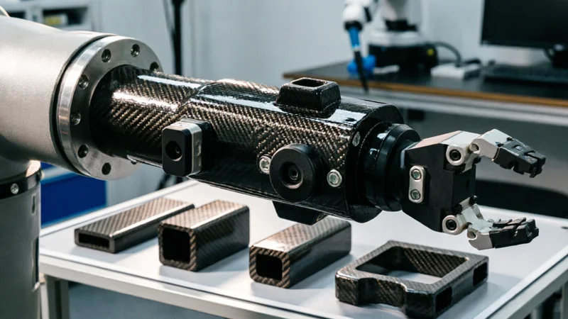
Carbon Fiber Robot End Effector Link — Custom Shape & Sensor Integration
Custom-shaped carbon fiber end effector links for robotic arms. Designed for automation integrators and research labs requiring lightweight, rigid connections between the robot wrist and gripper/tool. Can incorporate sensor mounting bosses, cable routing channels, and quick-change interfaces.
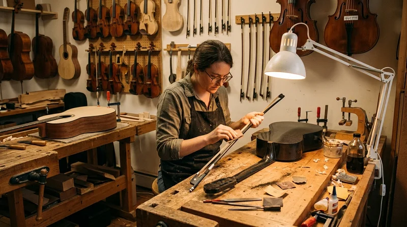
Custom Carbon Fiber Musical Instrument Parts
Carbon fiber components for musical instrument manufacturing offering superior dimensional stability, low weight, and consistent acoustic properties. We produce carbon fiber bows, guitar necks, violin chin rests, drum shells, and wind instrument bodies. Carbon fiber instruments are immune to humidity changes and temperature fluctuations that affect wooden instruments.
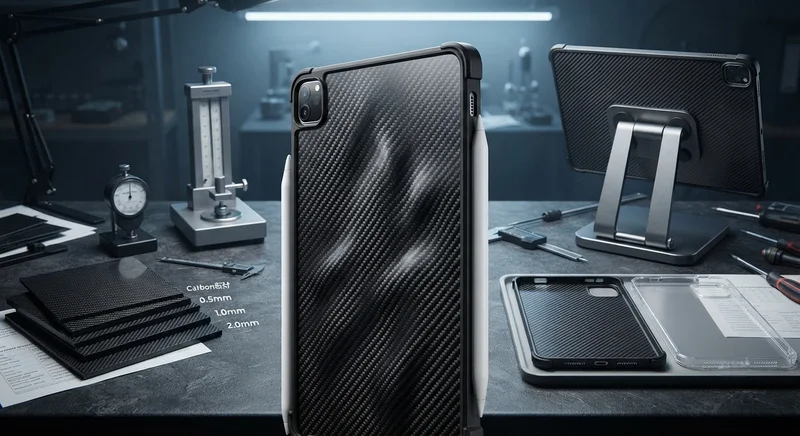
Carbon Fiber Tablet Case — Ultra-Light Protective Shell
Lightweight carbon fiber protective case for tablets and iPads. Molded from T700 3K prepreg with reinforced corner protection. Adds minimal weight while providing superior rigidity and drop protection compared to polycarbonate or silicone cases. Ideal for field workers, enterprise deployments, and professionals requiring durable tablet protection.
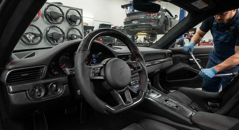
Carbon Fiber Steering Wheel — Custom Leather-Wrapped with CF Inlay
Custom carbon fiber steering wheel with genuine leather wrapping and carbon fiber inlay sections. Molded from T700 3K prepreg for maximum rigidity with a 30% weight reduction over OEM wheels. Available in D-shape (flat bottom) and round profiles. Direct bolt-on fitment for popular sports car and performance vehicle models. Custom stitching color and leather grade available.