
The aviation industry's commitment to net-zero carbon emissions by 2050 has accelerated electric and hybrid-electric propulsion from concept to certification timeline. The fundamental challenge is energy density: lithium-ion batteries deliver approximately 250 Wh/kg, while jet fuel provides 12,000 W
Introduction
The aviation industry's commitment to net-zero carbon emissions by 2050 has accelerated electric and hybrid-electric propulsion from concept to certification timeline. The fundamental challenge is energy density: lithium-ion batteries deliver approximately 250 Wh/kg, while jet fuel provides 12,000 Wh/kg — a 48:1 disadvantage that makes every kilogram of structural weight critical. Carbon fiber composites are not merely an optimization for electric aircraft; they are an enabling technology without which electric flight cannot achieve viable range and payload.
Electric motor housings, nacelle structures, and thermal management enclosures represent the structural components where carbon fiber delivers the most direct performance impact. These components must simultaneously provide electromagnetic shielding, structural load paths, thermal management interfaces, and acoustic damping — all while weighing as little as possible. This article analyzes the design requirements, material solutions, and quantified weight savings that are making carbon fiber composites indispensable to electric aircraft propulsion.
Why Electric Aircraft Need Carbon Fiber
Electric propulsion imposes uniquely demanding weight constraints that conventional metal structures cannot meet efficiently. The weight sensitivity of battery-powered aircraft creates a self-reinforcing problem: heavier structures require larger batteries, which require stronger structures, which are heavier still. Carbon fiber breaks this cycle through several mechanisms:
- Specific strength advantage: Carbon fiber composites offer tensile strength of 1,500-3,500 MPa at densities of 1.5-1.6 g/cm³, compared to aluminum alloys at 300-550 MPa at 2.7 g/cm³. The specific strength ratio of 2.5-6.5:1 directly translates to structural weight savings.
- Design freedom: Composites can be molded into complex aerodynamic shapes — motor housings, nacelle fairings, duct geometries — that would require multiple machined and fastened metal components, eliminating assembly joints and fastener weight.
- Integrated functionality: Carbon fiber structures can incorporate electromagnetic shielding (via conductive fiber architectures), thermal management channels (via embedded cooling circuits), and acoustic damping (via viscoelastic interlayers) in a single cured part.
- Fatigue resistance: Electric motors produce high-frequency torque pulses that create cyclic loading on motor mounts. Carbon fiber composites exhibit superior fatigue resistance compared to aluminum, extending inspection intervals and reducing maintenance weight.
Carbon Fiber Motor Housing Design
The electric motor housing in an aircraft propulsion system serves multiple functions simultaneously: it contains the electromagnetic fields, provides the structural mount to the airframe, dissipates motor heat, and contributes to acoustic noise reduction. Carbon fiber motor housings are designed using several architectural approaches:
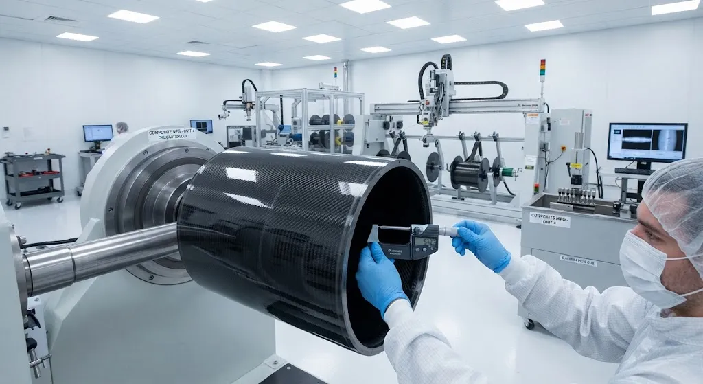
- Filament-wound cylindrical housings: The most common approach for high-power motors (>200 kW). Carbon fiber tow is wound helically over a mandrel, creating a seamless cylindrical shell with controlled fiber orientation. The winding angle is optimized for the combined hoop stress (from electromagnetic forces) and axial stress (from motor torque reaction). Typical wall thickness: 2-4 mm, weight: 3-8 kg for a 200 kW motor housing.
- Prepreg layup housings: Used for complex geometries with integrated cooling channels, mounting flanges, and sensor ports. Automated fiber placement (AFP) enables local thickness variation to match stress distribution, optimizing the weight-to-stiffness ratio. Wall thickness varies from 1.5 mm at low-stress zones to 6 mm at load introduction points.
- Hybrid metal-composite housings: An aluminum or titanium inner liner provides electromagnetic shielding and thermal conductivity, while a carbon fiber outer shell provides structural strength. This approach combines the best properties of both materials at a moderate weight penalty (10-15% heavier than pure composite).
The design challenge is managing the electromagnetic-thermal-structural interaction. Motor housings must provide sufficient electromagnetic shielding to prevent interference with avionics while maintaining thermal conductivity high enough to dissipate motor waste heat (typically 5-8% of electrical input power). Carbon fiber with intermediate modulus (IM) fibers and pitch-based carbon fiber overwraps address both requirements.
Nacelle Structures for Electric Propulsion
Electric aircraft nacelles differ fundamentally from turbofan nacelles. They house electric motors instead of combustion engines, requiring different inlet geometries, thermal management integration, and structural load paths. Carbon fiber nacelle design for electric propulsion addresses three primary functions:
- Structural load path: The nacelle transmits motor thrust to the wing or fuselage structure. In distributed electric propulsion (DEP) configurations with multiple small motors, the nacelle structure must handle thrust loads, gyroscopic loads from propeller/rotor imbalance, and bird-strike or FOD impact loads — all at minimum weight.
- Thermal management housing: Electric motors and power electronics generate significant waste heat. The nacelle integrates liquid cooling channels, heat exchangers, and ventilation pathways. Carbon fiber nacelle panels with embedded aluminum cooling plates or additive-manufactured titanium thermal接口 provide the thermal conductivity path without adding excessive weight.
- Acoustic optimization: Electric motors produce tonal noise at specific frequencies. Carbon fiber nacelle structures with tuned acoustic liners (honeycomb core with resistive face sheets) attenuate motor noise by 15-25 dB, critical for urban air mobility operations where community noise limits are strict.
Performance Data: Weight Savings
The weight savings from carbon fiber in electric aircraft components are quantified across several structural categories:
| Component | Aluminum Baseline (kg) | Carbon Fiber (kg) | Weight Saving | Application |
|---|---|---|---|---|
| 200 kW motor housing | 12-18 | 4-8 | 55-65% | eVTOL, regional electric |
| Nacelle structure (per motor) | 25-40 | 10-18 | 55-60% | DEP configurations |
| Battery enclosure frame | 45-70 | 20-35 | 50-55% | All-electric aircraft |
| Thermal management ducting | 8-15 | 3-6 | 60-65% | Power electronics cooling |
| Motor mount pylon | 15-25 | 6-10 | 60-60% | Wing-mounted motors |
Cumulative weight savings across the propulsion system typically reach 40-55% compared to aluminum construction. For a regional electric aircraft with 8-12 distributed motors, total propulsion structure weight savings of 200-400 kg translate directly into 15-25% additional battery capacity or equivalent range extension.
Thermal Management Integration
Thermal management is one of the most challenging aspects of electric aircraft design. A 1 MW electric propulsion system generates 50-80 kW of waste heat that must be rejected to the ambient air. Carbon fiber structures play a critical role in the thermal management chain:
- Embedded cooling channels: Carbon fiber nacelle panels with co-cured aluminum or titanium cooling tubes provide direct thermal paths from motor surfaces to ram-air heat exchangers. The coefficient of thermal expansion (CTE) mismatch between carbon fiber (near-zero CTE) and metals (23 ppm/°C for aluminum) is managed through compliant interlayer materials.
- Heat sink structures: Carbon fiber sandwiches with metal foam cores or graphite-filled resin matrices serve as distributed heat sinks, spreading thermal loads across large surface areas for efficient convection.
- Thermal interface materials: Carbon fiber surfaces with controlled roughness and surface energy optimize thermal contact with motor housings, reducing thermal resistance at the motor-to-nacelle interface.
eVTOL and Urban Air Mobility Applications
The urban air mobility (UAM) market is the most active adopter of carbon fiber for electric propulsion structures. Leading eVTOL developers specify carbon fiber composites for:
- Motor nacelles and pylons: Every major eVTOL program (Joby S4, Lilium Jet, Archer Midnight, EHang 216) uses carbon fiber motor nacelles and mounting pylons, with typical weight fractions of 40-55% for these assemblies.
- Propeller and rotor blades: Carbon fiber composite blades for eVTOL rotors must withstand high rotational speeds (1,500-3,000 RPM), bird-strike requirements, and acoustic constraints. Filament-wound or prepeg-autoclave blades achieve 30-40% weight reduction versus aluminum.
- Fuselage and wing structures: While not exclusively propulsion components, the carbon fiber fuselage and wing structures of eVTOL aircraft are designed to accommodate distributed propulsion integration, with motor mount hardpoints co-cured into the primary structure.
Frequently Asked Questions
How does carbon fiber motor housing weight compare to direct-drive versus geared electric motors?
Direct-drive motors (no gearbox) require larger diameter motor housings to achieve the required torque, resulting in higher housing weight (6-12 kg for a 200 kW direct-drive motor). Geared motors use smaller, higher-speed motors with proportionally smaller housings (3-6 kg for the motor, plus 2-4 kg for the gearbox). Carbon fiber housings for geared systems achieve the best absolute weight savings because the smaller motor diameter allows thinner, lighter composite shells. The total drivetrain weight (motor + gearbox + housing) for geared systems is typically 15-25% lower than direct-drive at equivalent power output.
What certifications apply to carbon fiber electric propulsion structures?
Carbon fiber electric propulsion structures must comply with FAA Part 23/25 (structural requirements), Part 33 (engine/propulsion), and the emerging electric aircraft special conditions. Key certification considerations include flammability testing (FAR 25.853), bird-strike resistance (FAR 25.775), and electromagnetic compatibility (DO-160 Section 21/22). For eVTOL aircraft, additional requirements include crashworthiness (transition and landing scenarios) and noise certification under ICAO Annex 16. Carbon fiber composites simplify certification in some areas — fatigue test programs are shorter than for aluminum — but add complexity in others, such as lightning strike protection and impact damage tolerance.
What is the cost comparison between carbon fiber and aluminum motor housings for electric aircraft?
Carbon fiber motor housings cost 2-4x more than equivalent aluminum housings on a per-part basis, driven by material cost ($80-200/kg for aerospace-grade carbon fiber vs $5-15/kg for aerospace aluminum), tooling cost ($50,000-200,000 for AFP/filament winding tools), and longer cycle times. However, the weight savings translate to reduced battery requirements: every kilogram of structural weight saved allows approximately 0.3-0.5 kg less battery capacity needed for equivalent range, which at battery costs of $150-300/kWh represents $45-150 of battery cost savings per kilogram of structural weight saved. For high-production-rate programs (>500 units/year), carbon fiber housings approach cost parity with aluminum when total system cost (structure + battery) is considered.
Conclusion
Carbon fiber composites are not optional for electric aircraft propulsion — they are structurally necessary. The 55-65% weight savings in motor housings, 50-60% in nacelle structures, and 40-55% cumulative savings across the propulsion system directly determine whether an electric aircraft achieves viable range and payload. Beyond weight, carbon fiber enables integrated thermal management, electromagnetic shielding, and acoustic optimization that metal structures cannot match without prohibitive weight penalties.
As the eVTOL and regional electric aircraft markets scale from prototype to certification and production in 2027-2030, carbon fiber demand from electric propulsion alone is projected to reach 5,000-10,000 metric tons per year. For material suppliers and component manufacturers, the electric aircraft market represents the fastest-growing high-value application for carbon fiber composites. Explore our carbon fiber prepreg and fabric range suitable for aerospace motor housings and nacelle structures, or contact our aerospace solutions team to discuss material specifications and qualification for electric propulsion applications.
Part of topic
Related Articles
- Carbon Fiber Reusable Launch Vehicle Structures: Thermal Protection and Structural Integrity
- Carbon Fiber Underwater Robots and AUVs: Hydrostatic Pressure and Corrosion Resistance
- Carbon Fiber Mooring for Floating Offshore Wind: Fatigue and Corrosion in Deep Water
- Carbon Fiber Bicycle Frame Optimization: Layup Design and Manufacturing for Competitive Racing
- Carbon Fiber CFRP Retrofit for Infrastructure: Bridge and Building Seismic Strengthening
- Carbon Fiber Medical Imaging Equipment: Lightweight Gantry and Couch Structures for MRI/CT
Interested in Our Products?
Contact our team for competitive pricing and technical specifications.
Get a QuoteRelated Products

Carbon Fiber Plate — 3K Twill T700 1.5mm
Thin 1.5mm carbon fiber plate with 3K twill weave surface. Lightweight and stiff, commonly used for covers, panels, drone bodies, and applications requiring a premium aesthetic appearance.

Carbon Fiber Plate — 3K Twill T700 3.0mm
Medium-thickness 3.0mm carbon fiber plate offering significantly higher load capacity while maintaining attractive 3K twill finish. Suitable for structural brackets, reinforcement plates, and load-bearing panels.

Square Carbon Fiber Tube — 3K Twill T700
Square cross-section carbon fiber tube manufactured with 3K twill weave for torsional strength. Preferred for structural frames, trusses, and support columns where rectangular geometry offers design flexibility.

Carbon Fiber Plate — UD Unidirectional T700
Unidirectional carbon fiber plate with all fibers oriented in a single direction for maximum strength along the fiber axis. Essential for structural reinforcements, splints, and applications where load direction is predictable.

Round Carbon Fiber Tube — UD Unidirectional T700
Unidirectional (UD) round tube with all fibers aligned axially for maximum longitudinal stiffness. Ideal for applications requiring high bending rigidity with minimal weight, such as shafts, struts, and structural reinforcements.