
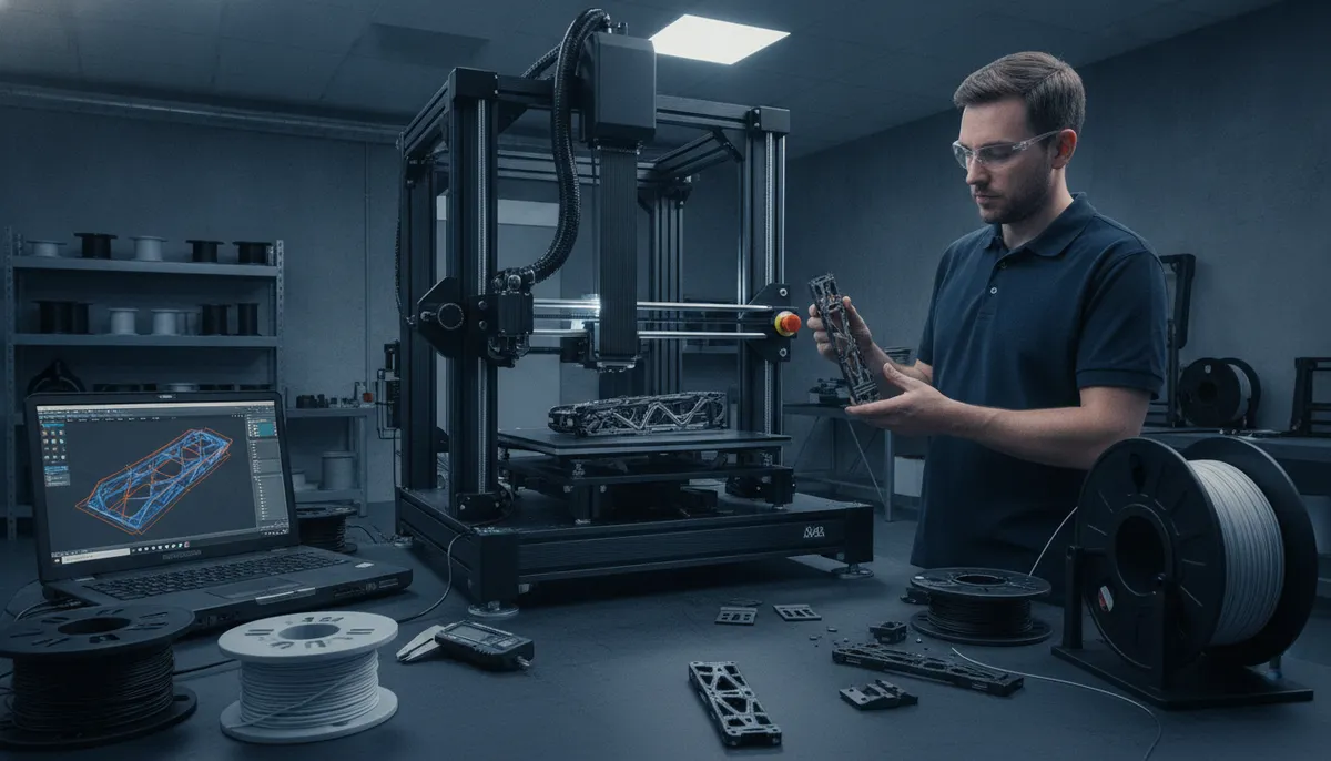
Continuous carbon fiber 3D printing has evolved from a prototyping curiosity to a legitimate manufacturing technology for structural composite components. Unlike chopped-fiber-filled filaments that provide only modest stiffness improvements over neat polymer, continuous fiber systems em
Introduction
Continuous carbon fiber 3D printing has evolved from a prototyping curiosity to a legitimate manufacturing technology for structural composite components. Unlike chopped-fiber-filled filaments that provide only modest stiffness improvements over neat polymer, continuous fiber systems embed unidirectional carbon fiber tows within a thermoplastic matrix, producing parts with specific stiffness approaching that of aluminum. The technology is finding adoption in tooling, fixtures, low-volume structural brackets, and aerospace interior components where the economics of small-batch production favor additive over conventional composite processes.
For carbon fiber manufacturers and buyers, understanding this technology is important for two reasons. First, continuous fiber printing consumes high-performance carbon fiber — T700S and T800S grades — creating a new demand vector beyond traditional aerospace and industrial applications. Second, the technology is reshaping how engineers think about composite part design, enabling geometries that are impossible with traditional layup or molding processes. This article examines the principal printing technologies, quantifies achievable mechanical properties, reviews current aerospace qualification status, and evaluates the market trajectory through 2030.
Printing Technologies for Continuous Fiber
Three principal technologies dominate continuous carbon fiber 3D printing, each with distinct capabilities and limitations:
- Fused Deposition Modeling (FDM) with fiber placement: Markforged pioneered this approach with their Mark Two and X7 systems, which deposit continuous carbon fiber, fiberglass, or Kevlar within a nylon matrix using a specialized print head. Layer resolution of 0.125 mm, fiber volume fraction of 30-40%, and build volumes up to 520 × 360 × 340 mm. This is the most commercially mature continuous fiber printing technology.
- Continuous fiber placement (CFP):** Systems from Anisoprint and ChroNoN use a co-extrusion process where continuous fiber is impregnated with resin during deposition, enabling higher fiber volume fractions (50-60%) and wider material selection. Anisoprint's Composer A3 uses a dual-nozzle system that places fiber and matrix simultaneously, achieving fiber volume fractions closer to traditional composites.
- In-situ consolidation: Research systems from universities and national labs use laser or induction heating to consolidate continuous fiber/thermoplastic tapes during placement, potentially eliminating the need for post-deposition autoclave cure. This approach is still in development but promises the highest fiber volume fractions and mechanical properties.
The choice between these technologies depends on the structural requirements of the target application, production volume, and geometric complexity.
Material Systems and Mechanical Properties
The mechanical properties achievable with continuous carbon fiber printing depend on fiber grade, matrix system, and printing parameters:
| Property | Continuous CF/PA (FDM) | Continuous CF/PEEK | 2D Prepreg Autoclave |
|---|---|---|---|
| Fiber volume fraction | 30-40% | 40-50% | 55-65% |
| Tensile strength (0°) | 600-800 MPa | 800-1,100 MPa | 1,500-2,000 MPa |
| Tensile modulus (0°) | 55-75 GPa | 70-100 GPa | 130-180 GPa |
| Specific stiffness (E/ρ) | 40-55 GPa·cm³/g | 50-70 GPa·cm³/g | 75-100 GPa·cm³/g |
| Interlaminar shear strength | 20-30 MPa | 35-50 MPa | 60-90 MPa |
| Void content | 3-8% | 2-5% | 0.5-2% |
| Service temperature (continuous) | 80-120°C (PA) | 200-260°C (PEEK) | 120-180°C (epoxy) |
The key insight is that continuous fiber 3D printing achieves 40-60% of the mechanical properties of autoclave-cured prepreg at fiber volume fractions that are 50-75% of prepreg levels. For many structural applications — brackets, fixtures, tooling, interior components — this performance level is adequate, and the geometric freedom and low tooling cost of additive manufacturing outweigh the property penalty.
Applications in Production
Continuous carbon fiber 3D printing is moving from prototyping to production across several sectors:
- Aerospace tooling and fixtures: The largest current application — jigs, fixtures, and assembly aids that replace aluminum tooling at 40-60% weight reduction. Aerospace OEMs including Boeing, Airbus, and Lockheed Martin use Markforged systems for production tooling.
- Structural brackets and fittings: Low-volume aerospace brackets (10-500 units/year) benefit from additive manufacturing's elimination of hard tooling. GE Aviation has qualified 3D-printed CF brackets for engine accessories.
- Drone and UAV structures: The most dynamic application area — drone frames, motor mounts, and payload structures benefit from the weight savings and rapid design iteration enabled by continuous fiber printing.
- Automotive prototyping and small-series: Racing teams and specialty vehicle manufacturers use continuous fiber printing for functional prototypes and limited-production structural components.
- Robotics and automation: Lightweight robot arms, end effectors, and custom grippers leverage continuous fiber printing's ability to optimize stiffness-to-weight ratios for specific motion profiles.
Aerospace Qualification Status
Aerospace qualification of continuous fiber 3D printing is progressing through several pathways:
- FAA DER approvals: Several FAA Designated Engineering Representatives have approved continuous fiber 3D-printed parts for non-structural and secondary structural applications, with primary structural qualification under development.
- NASA and ESA programs: NASA's Marshall Space Flight Center and ESA's Technology Centre have qualified continuous fiber printed components for CubeSat structures and ground support equipment, establishing test databases for higher-tier qualification.
- Boeing/Airbus research: Both OEMs are evaluating continuous fiber printing for interior cabin components and non-load-bearing structures, with qualification timelines of 2027-2029 for production applications.
- Material qualification: The critical bottleneck is establishing statistically significant material allowables (A/B-basis values) for continuous fiber printed laminates, which requires extensive testing campaigns and material lot variation data that are still accumulating.
The qualification pathway is analogous to the early days of RTM and out-of-autoclave processing — initial applications in non-critical areas build the test database and manufacturing confidence needed for structural applications.
Market Trajectory and Cost Analysis
The continuous fiber 3D printing market is projected to grow from $280M (2025) to $1.2B by 2030, driven by aerospace tooling, drone structures, and industrial automation applications. Cost per part analysis reveals the crossover points where additive manufacturing becomes competitive with traditional composite processes:
- Below 50 units/year: Continuous fiber printing is cost-competitive with RTM and compression molding when tooling costs exceed $10,000 — the typical threshold for steel or aluminum hard tooling.
- 50-500 units/year: Hybrid approaches combine 3D-printed tooling with traditional composite production, leveraging additive's tooling cost advantage while achieving prepreg-level mechanical properties.
- Above 500 units/year: Traditional composite processes (prepreg-autoclave, RTM) dominate on per-part cost, but additive manufacturing retains advantages for design optimization and rapid design changes.
For carbon fiber suppliers, the key opportunity is supplying high-quality continuous tow (T700S, T800S) to the additive manufacturing market, which requires consistent fiber sizing, tight tow width tolerances, and compatibility with thermoplastic impregnation processes.
Frequently Asked Questions
How do the mechanical properties of continuous fiber 3D printed parts compare to injection molded short-fiber composites?
Continuous fiber 3D printed parts significantly outperform injection molded short-fiber composites in stiffness-critical applications. Continuous CF/PA (nylon) achieves tensile modulus of 55-75 GPa versus 10-20 GPa for 30% short carbon fiber reinforced PA — a 3-5x improvement. The difference is even more pronounced in bending stiffness, where continuous fiber's unidirectional architecture provides directional reinforcement that chopped fibers cannot match. However, injection molding offers isotropic properties, higher production rates, and lower per-part cost for high volumes (1,000+ units). The choice depends on whether the application requires directional stiffness (favoring continuous fiber printing) or isotropic properties (favoring injection molding).
What are the main limitations of continuous fiber 3D printing for structural applications?
Three limitations are most commonly cited. First, fiber volume fraction (30-50%) is lower than prepreg-autoclave (55-65%), reducing absolute mechanical properties. Second, void content (2-8%) is higher than autoclave-cured composites (0.5-2%), affecting interlaminar properties and fatigue performance. Third, the thermoplastic matrix (PA, PEEK) provides different environmental resistance than thermoset epoxy systems, requiring qualification for specific service environments. Additionally, build size limitations (typically <600 mm in any dimension) restrict the size of printable structures, and print speeds (10-50 mm/s) are slower than automated fiber placement for large parts.
Can continuous fiber 3D printed parts be repaired or modified after printing?
Continuous fiber 3D printed parts with thermoplastic matrices (PA, PEEK) can be repaired or modified using several approaches. Localized re-melting and overprinting can add material to damaged areas, with fiber continuity maintained if the repair area overlaps with existing fiber paths. Surface machining can refine dimensions or create features that printing cannot achieve. For PEEK-based systems, thermal welding can join printed components to other PEEK structures. However, repair qualification for aerospace applications requires demonstration that repaired properties meet original design allowables, which is still under development for most continuous fiber printing systems.
Conclusion
Continuous carbon fiber 3D printing has matured from a technology demonstration to a production-capable manufacturing process, with aerospace tooling, structural brackets, and drone structures as the primary applications. The technology consumes T700S and T800S grade carbon fiber at fiber volume fractions of 30-50%, achieving specific stiffness values of 40-70 GPa·cm³/g that are competitive with aluminum and adequate for many structural applications. With aerospace qualification progressing through FAA, NASA, and OEM research programs, continuous fiber printing is positioned to capture $1.2B of the composites market by 2030.
For carbon fiber suppliers and buyers, understanding this technology is essential for serving the growing additive manufacturing market and for recognizing how additive processes may complement or compete with traditional composite manufacturing in your supply chain. Explore our carbon fiber tow and fabric portfolio, or contact our engineering team to discuss material specifications for continuous fiber 3D printing applications.
Related Articles
- Filament Wound Epoxy Tubes Advantages: Over Metal and Pultruded Alternatives
- Carbon Fiber Tube Strength: Analysis Methods and Design Allowables
- Filament Wound Epoxy Tubes: Mechanical Properties and Material Data Sheets
- Carbon Fiber Drone Blades and Propellers: Stiffness, Balance and Noise Reduction
- Fiberglass Filament Wound Tubes: Cost-Effective Alternative to Carbon Fiber
- Filament Wound Epoxy Tube Design: Wall Thickness, Fiber Angle and Load Optimization
Interested in Our Products?
Contact our team for competitive pricing and technical specifications.
Get a QuoteRelated Products
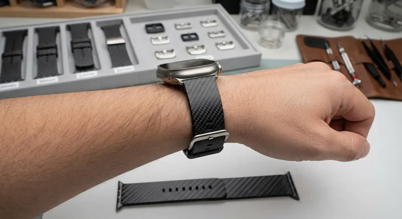
Carbon Fiber Watch Strap — 20mm/22mm Quick-Release
Premium carbon fiber watch strap with quick-release spring bars. Woven from T700 3K twill prepreg with a flexible resin system that conforms to the wrist. Available in 20mm and 22mm lug widths, compatible with Apple Watch, Samsung Galaxy Watch, Garmin, and traditional mechanical watches. Features a stainless steel buckle and carbon fiber keepers. The natural weave pattern makes each strap unique.

Carbon Fiber Fishing Rod Blank
High-quality carbon fiber fishing rod blank manufactured from multiple grades of Toray carbon fiber cloth. Available in a wide range of lengths, powers, and actions for freshwater and saltwater applications. Suitable for OEM rod building.

Carbon Fiber Plate — 3K Twill T700 1.5mm
Thin 1.5mm carbon fiber plate with 3K twill weave surface. Lightweight and stiff, commonly used for covers, panels, drone bodies, and applications requiring a premium aesthetic appearance.

Carbon Fiber Plate — 3K Twill T700 3.0mm
Medium-thickness 3.0mm carbon fiber plate offering significantly higher load capacity while maintaining attractive 3K twill finish. Suitable for structural brackets, reinforcement plates, and load-bearing panels.
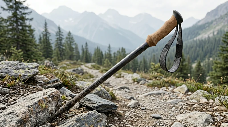
Carbon Fiber Trekking Pole
Lightweight carbon fiber trekking pole manufactured from high-grade carbon fiber tube. Weighs only 160g per pole while providing superior shock absorption and durability for hiking, trail running, and backpacking.