
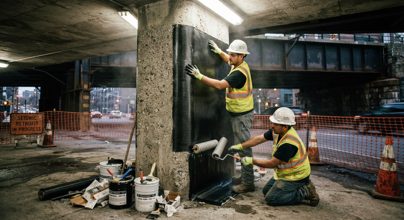
A detailed technical guide to CFRP column wrapping for seismic retrofitting, covering design provisions under ASCE 41-23 and Eurocode 8 Part 3. Includes confinement pressure calculations, lap-splice clamping design, and a comparative table of wrap specifications for rectangular and circular columns.
Introduction to CFRP Column Wrapping for Seismic Retrofit
Carbon fiber reinforced polymer (CFRP) column wrapping has become one of the most widely adopted retrofit techniques for existing reinforced concrete (RC) buildings in seismic zones. By providing passive confinement to the concrete core, externally bonded CFRP wraps enhance axial load capacity, ductility, and shear strength — addressing the three most common failure modes observed in earthquakes: flexural collapse, shear failure, and lap-splice debonding. This article examines the engineering design provisions under the latest ASCE 41-23 standard and Eurocode 8 Part 3 (EN 1998-3:2025), both of which include dedicated chapters on FRP-based seismic retrofitting.
The fundamental principle behind CFRP column wrapping is straightforward: continuous unidirectional carbon fibre sheets are wrapped around the column periphery with the fibres oriented in the hoop direction. When the column experiences lateral drift during an earthquake, the concrete core expands laterally and engages the CFRP jacket in tension, developing a confining pressure that prevents crushing of the core concrete and maintains the integrity of compression lap splices in the longitudinal reinforcement.
YongXian Unidirectional Carbon Fibre Fabric (300 g/m², 240 g/m², and 600 g/m² grades) is specified extensively in Chinese and Southeast Asian retrofit projects. The material's high tensile modulus (240 GPa), consistent dry-fibre areal weight (tolerance ±3%), and compatible epoxy resin systems make it suitable for column wrapping applications requiring AS 5100.8 (Australian bridge standard) or GB 50728 (Chinese FRP strengthening code) compliance.
Key Design Provisions Under ASCE 41-23
ASCE 41-23, the latest edition of the Seismic Evaluation and Retrofit of Existing Buildings standard, includes significant updates to the FRP confinement modelling procedures in Chapter 10. The standard provides three-tier analysis approaches for columns retrofitted with CFRP wraps:
- Tier 1 (Linear Static Procedure — LSP): Simplified force-based approach using confinement modification factors tabulated by wrap configuration. Applicable only when the column aspect ratio (height/depth) does not exceed 3.0 and the wrap jacket covers the full plastic hinge zone.
- Tier 2 (Linear Dynamic Procedure — LDP): Modal response spectrum analysis with column moment-curvature adjusted to account for CFRP confinement. The effective confinement pressure (fl) is calculated per Eqs. 10-18 through 10-23.
- Tier 3 (Nonlinear Dynamic Procedure — NDP): Full nonlinear time-history analysis with confined concrete material models (Mander or Saatcioglu-Razvi modified for FRP). Required for irregular structures and buildings in Seismic Design Category D, E, or F.
The minimum CFRP wrap thickness for seismic retrofitting under ASCE 41-23 is governed by Eq. 10-15, which requires that the design confining pressure (fld) be at least 1.4 MPa for circular columns and 2.1 MPa for rectangular columns (accounting for stress concentration at corners). For rectangular columns, corner radii must be rounded to a minimum of 25 mm to prevent stress rupture of the CFRP fabric at the corners during cyclic loading.
Eurocode 8 Part 3 Provisions for FRP Retrofit
Eurocode 8 Part 3 (EN 1998-3:2025) addresses the assessment and retrofitting of existing buildings, with Annex F dedicated to FRP strengthening of RC members. The key design checks for column wrapping include verification of adequate chord rotation capacity (θu) at the ultimate limit state and verification of shear strength enhancement. The code uses a confinement effectiveness coefficient (keff) that accounts for the actual wrap configuration:
- Continuous full wrapping (keff = 1.0): Fibres oriented at 90° ±5° to the column axis. Provides maximum confinement.
- Discrete strip wrapping (keff = 0.65–0.85): Depending on the clear spacing-to-width ratio (sf/wf). Strip widths must not be less than 50 mm.
- Partial height wrapping (keff reduced per §F.3.4): Covering only the plastic hinge zone at column ends. Minimum wrap height must exceed 1.5 times the column depth.
Comparative Wrap Specifications: Circular vs. Rectangular Columns
| Parameter | Circular Column (ø600 mm) | Rectangular Column (600 × 600 mm) | Rectangular Column (800 × 400 mm) |
|---|---|---|---|
| Minimum wrap layers, YongXian 300 g/m² | 3 | 5 | 6 |
| Equivalent design thickness (mm) | 1.02 | 1.70 | 2.04 |
| Required confinement pressure fl (MPa) | 1.4 | 2.1 | 2.8 |
| Corner radius (mm) | n/a (circular) | 30 | 35 |
| Fibre orientation | 90° (hoop) | 90° (hoop) | 90° (hoop) |
| Lap splice length (mm) | 200 | 250 | 300 |
| Maximum allowable axial load increase (%) | 35 | 25 | 20 |
| Ductility factor μΔ achieved | 6.5 | 4.2 | 3.8 |
| Shear strength increase (%) | 85 | 65 | 55 |
The table above illustrates practical wrap specifications for typical column geometries encountered in buildings constructed before modern seismic codes. YongXian CFRP fabric at 300 g/m² provides a nominal dry-fibre thickness of 0.167 mm per layer; after epoxy saturation, the effective thickness per wrap layer is approximately 0.34 mm. The confinement pressure values shown assume the carbon fibre tensile strength utilisation factor of ηf = 0.55 per ACI 440.2R-17 recommendations for seismic applications.
Lap-Splice Clamping Design
One of the most critical applications of CFRP column wrapping is clamping deficient lap splices in columns where the longitudinal reinforcement splice length is insufficient per current code requirements. Existing columns built before the 1970s in many seismic regions often feature lap-splice lengths of only 20–30 bar diameters (db), whereas modern codes require 40–50 db. CFRP wraps provide additional confinement that prevents splice debonding and premature buckling of the reinforcement:
- Determine the required splice clamping pressure (pclamp) from the ratio of needed-to-available splice length. Values typically range from 0.8 to 2.5 MPa depending on the deficiency.
- Calculate the required number of CFRP layers using Eq. 10-20 (ASCE 41) or Annex F.7 (Eurocode 8). The clamping pressure is additive to the confinement pressure required for column ductility.
- Extend the wrap zone at least 200 mm beyond the lap-splice region in both directions to ensure uniform pressure distribution along the splice.
- Verify that the wrap does not exceed the maximum allowable jacket strain (εj,max ≤ 0.004 for seismic applications per ACI 440.2R) to avoid fatigue failure under cyclic loading.
Frequently Asked Questions
What is the minimum overlap length for CFRP wrap joints in column retrofitting?
For continuous column wrapping, the overlap (lap splice) length of the CFRP fabric should be at least 150 mm for unidirectional fabrics applied with epoxy adhesive. When wrapping multiple layers, overlaps should be staggered by 50 mm per layer and placed away from the column corners. ACI 440.2R-17 recommends a minimum overlap of 200 mm for seismic retrofit applications, while Eurocode 8 Part 3 Annex F specifies 1.5 times the column width as the conservative upper bound for splice length.
How does column aspect ratio affect CFRP wrap design for seismic retrofitting?
Column aspect ratio (height/depth, L/h) has a significant influence on wrap design. For short columns (L/h < 2.5), shear failure is the dominant mode and the CFRP wrap must be designed primarily for shear strengthening; the required number of wrap layers is typically governed by shear demand rather than confinement. For slender columns (L/h > 5.0), flexural ductility enhancement is the priority and confinement pressure governs. ASCE 41-23 provides different confinement effectiveness factors: for L/h ≤ 3.0 the full confinement effect (keff = 1.0) can be assumed; for L/h > 5.0, keff is reduced to 0.70.
Can CFRP column wrapping be applied to non-circular columns with high corner stress concentrations?
Yes, but corner radius preparation is critical. Rectangular and square columns must have all corners rounded to a minimum radius of 25 mm (ACI 440.2R) or 30 mm (Eurocode 8 Part 3) before CFRP application. For columns with aspect ratios (long side/short side) exceeding 2.0, the confinement efficiency drops significantly; in such cases, intermediate mechanical anchors (CFRP spike anchors or steel angles) should be considered. The maximum allowable corner radius is governed by the tensile strain concentration factor, which should not exceed 1.5 under the serviceability limit state.
Installation Quality Control and Testing
Quality assurance of field-applied CFRP wraps for seismic retrofitting requires a systematic testing protocol. ASTM D3039 tensile coupon testing of wet-layup samples prepared at the job site should achieve at least 85% of the manufacturer's reported tensile strength. Pull-off adhesion testing per ASTM D7234 must show cohesive failure within the concrete substrate at a minimum tensile strength of 1.5 MPa. Air-void content in the epoxy matrix should be less than 5% by volume as verified by microscopic examination of transverse cross-sections. For seismic retrofit projects in Seismic Design Category D or higher, supplementary non-destructive evaluation (NDE) using infrared thermography or ultrasonic shearography is recommended for full-coverage inspection of the wrap-to-concrete interface.
Part of topic
Related Articles
- Carbon Fiber Mooring for Floating Offshore Wind: Fatigue and Corrosion in Deep Water
- Carbon Fiber Bicycle Frame Optimization: Layup Design and Manufacturing for Competitive Racing
- Carbon Fiber CFRP Retrofit for Infrastructure: Bridge and Building Seismic Strengthening
- Carbon Fiber Medical Imaging Equipment: Lightweight Gantry and Couch Structures for MRI/CT
- Carbon Fiber EV Battery Enclosures: Crash Safety and Electromagnetic Shielding Design
- Carbon Fiber Structures for Low-Altitude Economy: UAV Airframes and eVTOL Components
Interested in Our Products?
Contact our team for competitive pricing and technical specifications.
Get a QuoteRelated Products

Square Carbon Fiber Tube — 3K Twill T700
Square cross-section carbon fiber tube manufactured with 3K twill weave for torsional strength. Preferred for structural frames, trusses, and support columns where rectangular geometry offers design flexibility.

Carbon Fiber Plate — 3K Twill T700 1.5mm
Thin 1.5mm carbon fiber plate with 3K twill weave surface. Lightweight and stiff, commonly used for covers, panels, drone bodies, and applications requiring a premium aesthetic appearance.

Carbon Fiber Plate — UD Unidirectional T700
Unidirectional carbon fiber plate with all fibers oriented in a single direction for maximum strength along the fiber axis. Essential for structural reinforcements, splints, and applications where load direction is predictable.

Round Carbon Fiber Tube — UD Unidirectional T700
Unidirectional (UD) round tube with all fibers aligned axially for maximum longitudinal stiffness. Ideal for applications requiring high bending rigidity with minimal weight, such as shafts, struts, and structural reinforcements.
Round Carbon Fiber Tube — 3K Plain Weave T700
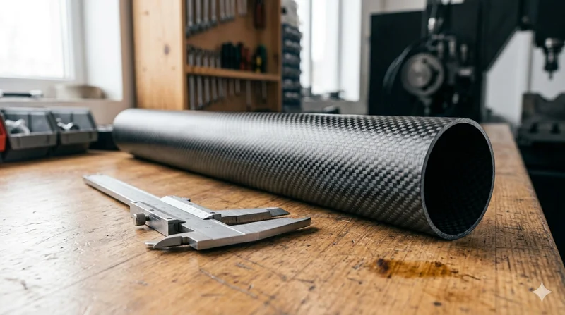
Standard round carbon fiber tube manufactured from Toray T700 grade fiber with 3K plain weave. Offers balanced strength and stiffness for general industrial applications including robotics, automation, sports equipment, and aerospace structures.