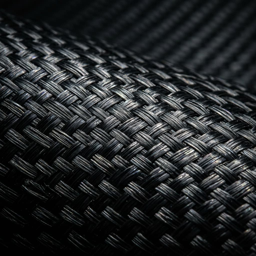
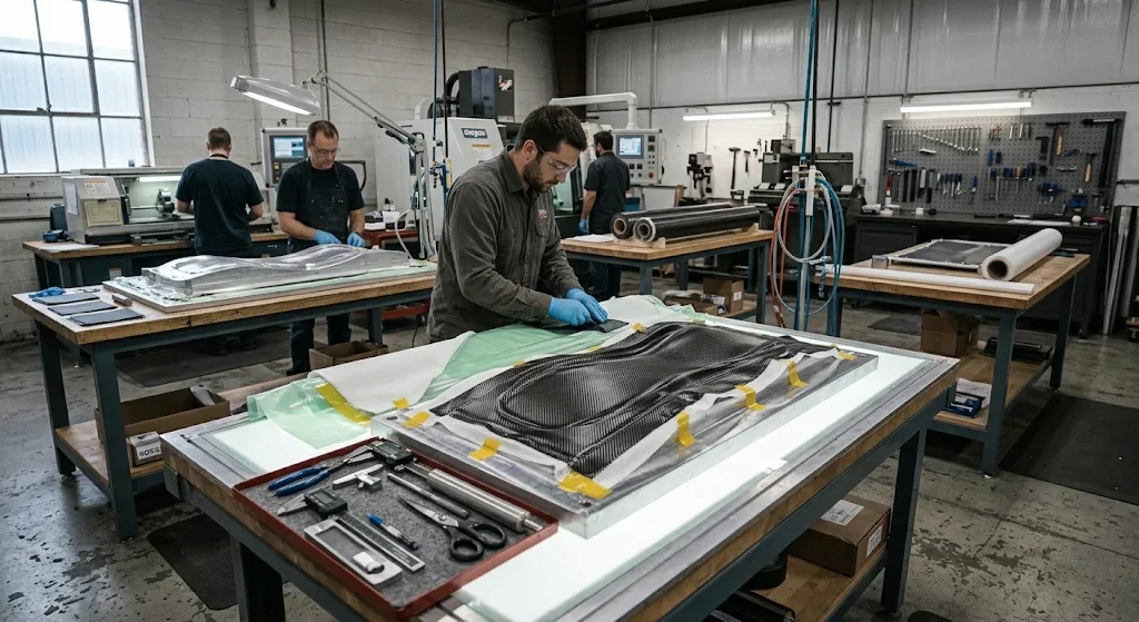
Understanding carbon fiber 1 plate requires a process-oriented view rather than focusing on a single step. Carbon fiber reinforced polymer (CFRP) parts combine high strength-to-weight ratio with design freedom, but achieving consistent results depends heavily on tooling, material selection, and cont
Introduction to Creating Carbon Fiber Parts
Understanding carbon fiber 1 plate requires a process-oriented view rather than focusing on a single step. Carbon fiber reinforced polymer (CFRP) parts combine high strength-to-weight ratio with design freedom, but achieving consistent results depends heavily on tooling, material selection, and controlled processing. This guide walks through each stage from initial tooling decisions to finishing and quality control, with practical data for scaling from one-off prototypes to repeatable production runs.
Tooling Strategies and Tradeoffs
The mold is the foundation when learning carbon fiber 1 plate because it determines surface quality, dimensional stability, and feasible cure cycles. Different tooling materials suit different volumes and temperature requirements. Choosing incorrectly leads to warpage, poor release, or excessive cost early in development.
| Tooling Type | Optimal Volume | Cycle Life | Max Temp | Relative Cost | Notes |
|---|---|---|---|---|---|
| 3D Printed PETG/CF | 1-3 parts | 1-5 cycles | ~70-80 °C | Low | Fast lead, limited for high temp resins |
| SLA with Epoxy Coating | 1-10 parts | 5-15 cycles | ~90-120 °C | Low-Mid | Smooth cosmetic surfaces, coating wear |
| Machined Aluminum 6061-T6 | 10-150 parts | 50-150 cycles | ~150-180 °C | Mid-High | Stable CTE, works well with oven and vacuum |
| Carbon/Epoxy Composite Tooling | 50-300 parts | 100-300 cycles | ~150-200 °C | High | Matched to part CTE, ideal for contoured autoclave parts |
| Tool Steel (P20/17-4) | 200+ parts | 200-500 cycles | ~200+ °C | Very High | Highest durability, longest machining time |
Mold Preparation and Release
Before layup, the mold surface must be clean, defect-free, and properly conditioned. Residual oils or worn release cause sticking and surface tearing. For most epoxy systems, thin, even coats of a compatible release agent applied per manufacturer guidance are critical. Some production molds use semi-permanent release systems to extend intervals between applications.
- Cleaning: Remove release buildup with approved solvents and inspect for scratches or pitting.
- Sealing: Porous molds or new 3D printed tools may require a mold sealer before release.
- Release application: Apply multiple thin coats, allow flash-off and cure between coats as specified.
- Verification: Perform a water-break test or wipe check to confirm uniform coverage.
Fiber Selection, Layup, and Debulking
Reinforcement choice drives stiffness, strength, and drapability. Unidirectional (UD) tapes deliver maximum strength along fiber direction, woven fabrics conform to curves and provide balanced properties, and non-crimp fabrics (NCF) offer optimized fiber paths with reduced crimp. Stack sequences must account for bending, torsion, and impact based on loading conditions.
Hand layup remains common for complex shapes and low volumes, while Automated Fiber Placement (AFP) and Automated Tape Laying (ATL) improve repeatability for larger, flatter parts. For hand layup, intermediate debulking at regular intervals compresses layers, removes trapped air, and prevents bridging over radii. Vacuum bagging is almost mandatory for production-quality parts as it applies uniform pressure during cure.
Curing: Oven, Autoclave, and Press Molding
Cure parameters must match the resin system datasheet exactly. Ramping too quickly causes exothermic spikes and internal stress; cooling too rapidly increases risk of warpage. Pressure is the key differentiator: vacuum-only provides consolidation, while autoclave pressure forces resin flow to reduce void content significantly.
| Process | Pressure | Typical Applications | Void Content | Surface Finish |
|---|---|---|---|---|
| Oven + Vacuum Bag | ~1 atm (vacuum) | Prototypes, enclosures, ducts | 1-3% | Good |
| Autoclave | 60-100 psi | Structural, aerospace, motorsport | <1% | Excellent |
| Compression/Press Molding | Varies (50-1000 psi) | High repeatability, net-shape features | <1% | Very consistent |
Trimming, Drilling, and Post-Processing
After cure, parts require trimming to net or near-net shape. Carbon fiber is abrasive, so use carbide-tipped or diamond-coated tooling. Drilling requires sharp bits, reduced feed rates, and support backing to minimize delamination at exit. For cosmetic parts, light sanding and polishing may be needed, while structural parts often go straight to inspection.
Quality Control and Inspection
Quality checks should cover both process and part. Track cure temperature/pressure profiles, vacuum integrity, and bagging materials for traceability. For critical parts, non-destructive testing (NDT) such as tap testing, ultrasonic C-scan, or thermography reveals internal defects. Dimensional inspection against CAD with calipers or CMM ensures fitment in assemblies.
- In-process: Vacuum holds, bag leaks, thermocouple readings, and debulk counts.
- Visual: Check for dry spots, bridging, wrinkles, resin-rich/rich areas, or print-through.
- NDT: Apply based on risk class; C-scan common for large structural laminates.
- Dimensional: Verify key features and critical datums after trimming.
Cost Considerations When Scaling
Tooling dominates upfront cost but amortizes with volume. Resin, fabric, and labor scale more linearly. For carbon fiber 1 plate, a practical approach is to prototype with inexpensive tooling, freeze geometry, then invest in durable tooling matched to expected cycle count. Factor in consumables (peel ply, breather, bag film), energy for cure, and post-processing labor when calculating part cost.
| Stage | Recommended Tooling | Typical Part Cost Range | Notes |
|---|---|---|---|
| Proof of concept (1-3) | 3D Printed/SLA | $150-$800/part | Speed over cost per part |
| Pilot (5-25) | Machined Aluminum | $80-$400/part | Balance of cost and repeatability |
| Low-mid production (25-150) | Aluminum or Composite Tooling | $40-$200/part | Amortize tooling over runs |
| Higher volume (150+) | Composite/Steel | $25-$150/part | Focus on cycle time and yield |
Practical Recommendations
- Design for manufacture: Avoid sharp internal corners and unworkable undercuts that complicate tooling.
- Match resin to process: Use oven-curing resins for vacuum/oven, or autoclave-grade systems when higher pressure is available.
- Document everything: Create a build sheet with ply book, bag schedule, and cure profile for repeatability.
- Plan for inspection: Define acceptance criteria early, especially for load-bearing features.
Conclusion
Mastering carbon fiber 1 plate is about making disciplined tradeoffs across tooling, materials, and processing. By selecting tooling appropriate to volume, following validated cure cycles, and enforcing quality control, manufacturers can produce strong, lightweight CFRP parts efficiently. For custom carbon fiber parts, tooling design, or process consulting, explore YongXian's composite manufacturing services to discuss your specific requirements.
Frequently Asked Questions
Q: Which tooling is best for a first carbon fiber prototype?
A: For a single prototype, SLA with epoxy coating or machined aluminum inserts offer the best balance of speed and surface quality. 3D printed tooling works for very simple shapes if cure temperatures are low.
Q: Do I need an autoclave to make quality carbon fiber parts?
A: No. Many parts achieve excellent results with oven curing and vacuum bagging. Autoclaves are mainly needed when lower void content and higher consistency are required for structural parts.
Q: How do I avoid delamination when drilling?
A: Use sharp carbide or diamond-coated bits, run at moderate speeds with lower feed, support the exit side with backing material, and avoid excessive pressure. Proper bagging and cure also reduce delamination risk.
Q: When should I switch from prototype tooling to production tooling?
A: Switch once geometry is frozen and you have a realistic volume forecast. If you expect more than ~15-25 parts and need consistent dimensions, investing in aluminum or composite tooling usually pays off.
Part of topic
Related Articles
- Carbon Fiber Composite Core Repair Service: Damage Assessment and Return to Service
- 4mm carbon fiber drone frame: When the Extra Wall Thickness Pays Off
- carbon fiber fishing rod Guide: Modulus, Guides, and Durability
- Carbon Fiber Rods for Fishing: Blank Selection for Builders
- Carbon Fiber Toe Plates: Rocker Design in Footwear
- Carbon Fiber Drones (carbon fiber drones): Airframes, Payloads, and Cost Impact
Interested in Our Products?
Contact our team for competitive pricing and technical specifications.
Get a QuoteRelated Products
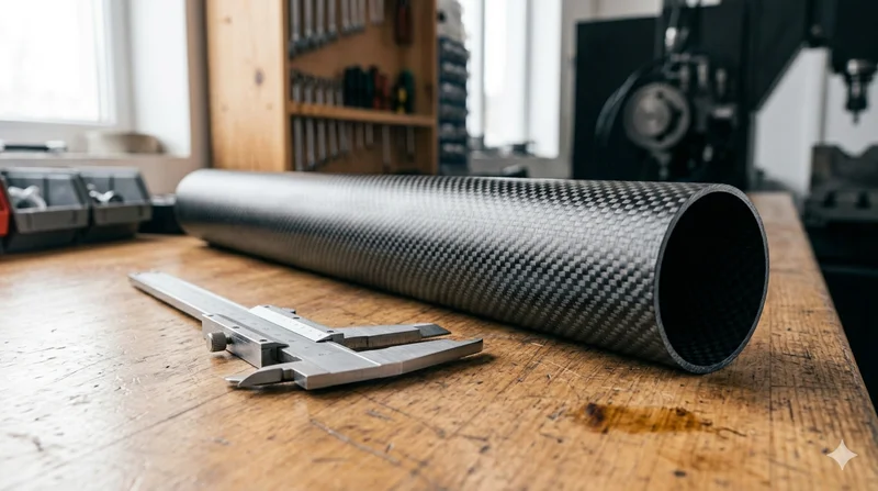
Round Carbon Fiber Tube — 3K Plain Weave T700
Standard round carbon fiber tube manufactured from Toray T700 grade fiber with 3K plain weave. Offers balanced strength and stiffness for general industrial applications including robotics, automation, sports equipment, and aerospace structures.
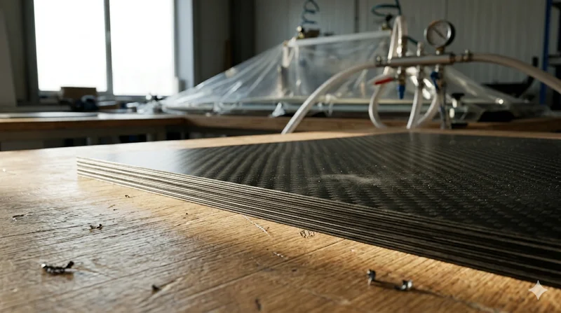
Carbon Fiber Plate — 3K Twill T700 3.0mm
Medium-thickness 3.0mm carbon fiber plate offering significantly higher load capacity while maintaining attractive 3K twill finish. Suitable for structural brackets, reinforcement plates, and load-bearing panels.
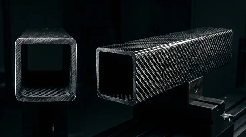
Square Carbon Fiber Tube — 3K Twill T700
Square cross-section carbon fiber tube manufactured with 3K twill weave for torsional strength. Preferred for structural frames, trusses, and support columns where rectangular geometry offers design flexibility.
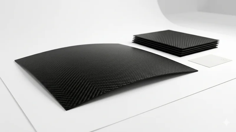
Carbon Fiber Plate — 3K Twill T700 1.5mm
Thin 1.5mm carbon fiber plate with 3K twill weave surface. Lightweight and stiff, commonly used for covers, panels, drone bodies, and applications requiring a premium aesthetic appearance.
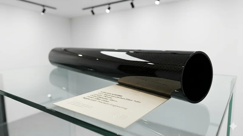
High Modulus Round Carbon Fiber Tube — M40
High modulus round tube manufactured with M40 grade fiber (tensile modulus 400 GPa). Designed for applications where maximum stiffness-to-weight ratio is critical, such as optical systems, precision machinery, and aerospace structures.