
The automotive driveshaft sits at the geometric center of the vehicle, yet its length and rotation speed place it at the heart of some of the most rigid constraints in driveline engineering. A steel tube that is too long for its diameter reaches its first bending critical speed inside t
Introduction
The automotive driveshaft sits at the geometric center of the vehicle, yet its length and rotation speed place it at the heart of some of the most rigid constraints in driveline engineering. A steel tube that is too long for its diameter reaches its first bending critical speed inside the operating range, flexing like a jump rope and producing vibration strong enough to damage bearings, joints and even the transmission output housing. This is why pickups, vans and SUVs with long wheelbases have traditionally used two-piece steel shafts with a center bearing rather than a single long tube. Carbon fiber changes the calculation. A carbon fiber automotive driveshaft can weigh up to 60 percent less than a steel equivalent, and its higher specific stiffness pushes the critical speed far beyond any engine or motor speed a road vehicle can generate — which is exactly why the technology has moved from racing paddocks into production vehicles.
This article explains the physics behind the critical speed limit, quantifies the mass and NVH advantages of a carbon fiber driveshaft with a comparison table, and reviews the two-piece integration question: when a single-piece carbon tube can replace a two-piece steel assembly, and which qualification and service realities still need to be managed in series production.
Why the Critical Speed Limit Exists
Every rotating shaft has a set of natural bending frequencies, and the first of them is called the critical speed. As rotation speed approaches that frequency, lateral deflection grows sharply, and small residual imbalance is amplified into large whirling vibration. Driveline engineers keep shafts below roughly 70 percent of the critical speed to leave a safety margin, so the practical length of a shaft is set not by strength but by this bending limit. The critical speed scales with the square root of the specific bending stiffness of the tube material. Steel has a specific modulus of about 26 GPa per g/cm³, aluminum about the same, while a balanced carbon fiber layup used in driveshaft construction offers roughly two to three times that value. The consequence is dramatic: a 1,500 mm one-piece steel tube has a first critical speed of about 3,500-4,200 rpm, an aluminum tube reaches roughly 4,500-5,000 rpm, and a carbon fiber tube of the same outer diameter and length can reach 7,500-9,000 rpm or more.
The operating implication is simple. Passenger vehicles commonly spin the driveshaft at 3,000-5,000 rpm in low gears and towing conditions, which is precisely the range where long steel one-piece shafts become marginal. Carbon fiber removes the constraint at the material level rather than through added bearings and joints, and that is the foundation of every benefit discussed below.
Mass, Performance and Cost: Carbon vs Steel vs Aluminum
The table below compares typical figures for a light-truck driveshaft of 1,250 mm tube length and 76 mm outer diameter, using production-representative values for a wound carbon fiber tube with aluminum yokes:
| Property | Steel (one-piece) | Aluminum (one-piece) | Carbon fiber (±45° wound) |
|---|---|---|---|
| Tube mass | 9.8 kg | 5.4 kg | 3.1 kg |
| First bending critical speed | ~4,000 rpm | ~4,800 rpm | ~8,500 rpm |
| Specific modulus (axial bending) | 26 GPa·cm³/g | 26 GPa·cm³/g | 55-75 GPa·cm³/g |
| Damping ratio | 0.05-0.2% | 0.1-0.3% | 0.5-1.5% |
| Continuous service temperature | 250°C+ | 150°C+ | 120-150°C (resin dependent) |
| Impact and overload behavior | Ductile, bendable | Ductile, bendable | Brittle, no straightening possible |
| Cost multiplier vs steel | 1.0x | 1.2-1.5x | 2.5-4.0x |
Two rows deserve emphasis. The mass saving of roughly 50-60 percent comes straight out of unsprung-correlated driveline inertia, improving acceleration feel and reducing loads on driveline bearings. The critical speed margin, meanwhile, is what makes longer single-piece carbon shafts feasible in platforms that previously required a two-piece steel arrangement.
NVH Behavior of a Carbon Fiber Driveshaft
Noise, vibration and harshness (NVH) is where carbon fiber shafts earn their reputation in luxury and performance vehicles. Three mechanisms combine. First, the higher damping ratio of a composite tube absorbs torsional vibration energy that a steel tube would transmit as noise; measured shaft whine and boom levels in instrumented vehicle tests are typically several dB lower at highway cruise. Second, because the critical speed moves well outside the operating band, the shaft's first bending mode is no longer a source of boom at 60-90 km/h in towing or low-gear operation. Third, the lower rotational inertia of the lighter tube reduces the torque spikes transmitted through universal joints when the driveline is loaded and unloaded, cutting the clunk and shuffle that engineers associate with two-piece steel layouts.
NVH tuning is not free. The composite tube's response depends on the layup, the tube diameter, and the balancing quality, and the aluminum yokes must be dynamically balanced with the tube as an assembly. Producing a consistently quiet carbon driveshaft requires balance targets in the range of 10-20 g·mm residual imbalance and careful control of shaft runout, which is why shaft suppliers keep dedicated spin-balancing stations with displacement sensors rather than relying on static balancing alone.
Two-Piece Integration and System-Level Savings
The most visible production trend is the replacement of two-piece steel assemblies with a single carbon tube, particularly in trucks, sports cars and electric platforms with long wheelbases. The system-level benefits are:
- Center bearing and hanger bracket elimination: A two-piece steel shaft carries its center bearing, bracket, rubber isolator and fasteners — typically 4-6 kg of mass that disappears entirely when a single carbon tube spans the same distance.
- Fewer joints, less slop: Two Cardan joints become one, removing a source of angularity loss, torsional compliance and maintenance attention.
- Tunnel and packaging freedom: The thinner, lighter carbon tube is easier to route in body tunnels, and the removal of the hanger bracket frees underbody space for exhaust and battery packaging.
- Long single-piece lengths: Carbon tubes of 2.0-2.6 m are in service where a one-piece steel tube of that length would be impossible; the material's specific stiffness makes critical speed a non-issue for most road applications.
- Reduced rotary inertia: Lower inertia improves shift quality in manuals and automated transmissions and reduces driveline load reversals, extending universal joint and seal life.
Factory carbon fiber driveshafts have appeared in high-performance models such as the BMW M3 and M4, the Dodge Viper, and several Corvette-based platforms, and the same integration logic is now being applied in battery-electric trucks and vans where the battery pack occupies the space a hanger bracket previously used.
Manufacturing: Filament Winding and Tube Architecture
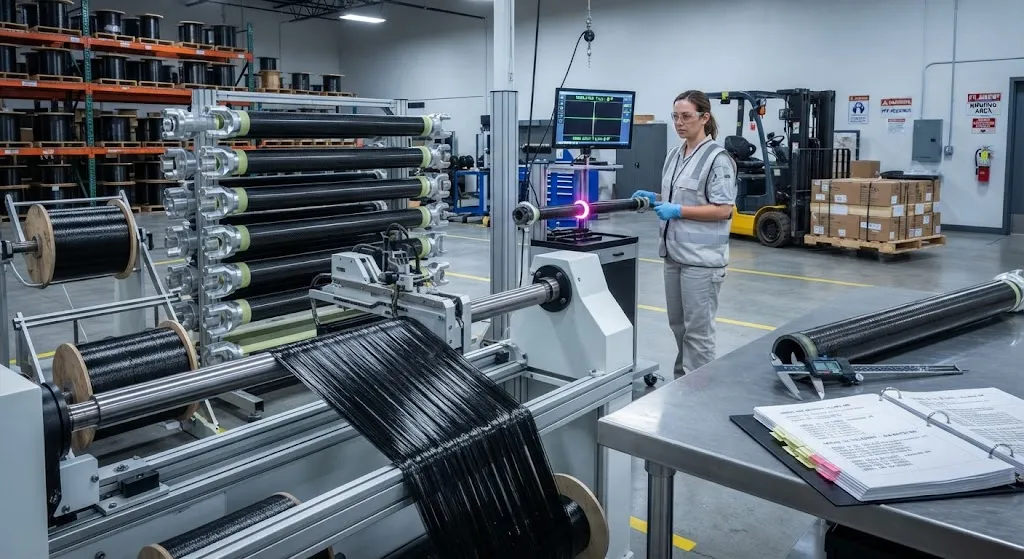
Production carbon driveshafts are almost always filament wound. Balance-angle layers at roughly ±45° provide the torsional stiffness that carries the majority of drive torque, while near-hoop layers add radial stiffness and resist tube ovalization under load. A typical tube uses 8-20 wound layers depending on torque class, with a fiber volume fraction of 55-62 percent and a thin outer surface veil that improves paint and stone-chip resistance. Aluminum yokes are adhesive-bonded and mechanically secured to the tube ends, with a galvanic isolation layer between the aluminum and the carbon to prevent corrosion in humidity and salt environments. After bonding, the shaft passes through cure, machining of the yoke faces, dynamic balancing and final runout inspection before assembly into the vehicle.
Qualification and Service Considerations
Adopting a carbon driveshaft changes the maintenance story compared with steel. A bent steel tube can be straightened or replaced cheaply; a damaged composite tube cannot be straightened and is usually replaced, so underbody impact protection and a clear service protocol matter. Wear from stone chips, heat from exhaust routing, and repeated exposure to salt spray all need to be addressed through surface coatings and system integration. Program qualification typically includes torsional fatigue testing to several times the design life, impact testing of the tube and yokes, thermal cycling across the operating temperature range, and corrosion testing of the bonded yoke interface. None of these are barriers to adoption — they are simply the engineering work that turns a race-proven material into a reliable production component.
Frequently Asked Questions
Why is a carbon fiber driveshaft quieter than a steel one?
There are three reasons. The composite tube has a damping ratio roughly five to ten times higher than steel, so torsional vibration energy is absorbed rather than transmitted as noise. The critical speed is far outside the operating range, so the first bending mode no longer produces boom at highway speeds. And the lower rotational inertia reduces the torque spikes that pass through the universal joints when the driveline loads and unloads, cutting clunk and shuffle. Together these effects typically lower measured cabin noise at cruise speed by several dB compared with a steel shaft of the same function.
Can a single-piece carbon shaft always replace a two-piece steel assembly?
Not automatically, but in most long-wheelbase platforms the answer is yes with proper engineering. The carbon tube must be sized for the torque class and critical speed requirement, and the driveline angles, tunnel clearance and joint interfaces must be verified, because removing the center bearing changes the driveline geometry and the structural load path of the hanger bracket. Electric and hybrid platforms are often the easiest candidates because their drivelines are shorter and cleaner. A full driveline study, including angle checks and NVH testing in the vehicle, is the professional way to confirm a conversion.
Are carbon fiber driveshafts safe if the tube gets damaged by a stone or a curb strike?
Yes, with the right design and inspection practice. The tube is protected by the outer surface veil, paint system and often a stone-guard shield in the underbody package, and the layered construction means minor superficial damage does not cause sudden failure. Any visible damage such as a deep gouge, cracked coating or impact mark should be inspected by the supplier or a trained shop; a damaged composite tube is replaced rather than straightened, because composite damage is internal and may not be visible from the outside. This is a well-understood maintenance regime that OEM programs specify in their service documentation.
Conclusion
Carbon fiber automotive driveshafts convert the material's high specific stiffness into a practical driveline advantage: a 50-60 percent mass saving, a critical speed ceiling high enough to eliminate two-piece steel constraints, measurable NVH improvement, and system-level benefits from removing the center bearing and hanger bracket. The technology is no longer exotic — factory installations in BMW M models, the Dodge Viper and Corvette platforms, and growing adoption in battery-electric trucks demonstrate that it is a series-production solution rather than a motorsport experiment.
For driveline and vehicle engineers evaluating carbon shafts, the practical starting points are torque class definition, tube architecture selection and NVH targets. Explore our carbon fiber tube and shaft material range with torque-rated architectures for automotive programs, or contact our engineering team to discuss shaft sizing, prototyping and qualification support for your platform.
Part of topic
Related Articles
- Carbon Fiber Mooring for Floating Offshore Wind: Fatigue and Corrosion in Deep Water
- Carbon Fiber Bicycle Frame Optimization: Layup Design and Manufacturing for Competitive Racing
- Carbon Fiber CFRP Retrofit for Infrastructure: Bridge and Building Seismic Strengthening
- Carbon Fiber Medical Imaging Equipment: Lightweight Gantry and Couch Structures for MRI/CT
- Carbon Fiber EV Battery Enclosures: Crash Safety and Electromagnetic Shielding Design
- Carbon Fiber Structures for Low-Altitude Economy: UAV Airframes and eVTOL Components
Interested in Our Products?
Contact our team for competitive pricing and technical specifications.
Get a QuoteRelated Products

Carbon Fiber Plate — 3K Twill T700 3.0mm
Medium-thickness 3.0mm carbon fiber plate offering significantly higher load capacity while maintaining attractive 3K twill finish. Suitable for structural brackets, reinforcement plates, and load-bearing panels.

Carbon Fiber Plate — 3K Twill T700 1.5mm
Thin 1.5mm carbon fiber plate with 3K twill weave surface. Lightweight and stiff, commonly used for covers, panels, drone bodies, and applications requiring a premium aesthetic appearance.

Square Carbon Fiber Tube — 3K Twill T700
Square cross-section carbon fiber tube manufactured with 3K twill weave for torsional strength. Preferred for structural frames, trusses, and support columns where rectangular geometry offers design flexibility.

Carbon Fiber Plate — UD Unidirectional T700
Unidirectional carbon fiber plate with all fibers oriented in a single direction for maximum strength along the fiber axis. Essential for structural reinforcements, splints, and applications where load direction is predictable.

Round Carbon Fiber Tube — UD Unidirectional T700
Unidirectional (UD) round tube with all fibers aligned axially for maximum longitudinal stiffness. Ideal for applications requiring high bending rigidity with minimal weight, such as shafts, struts, and structural reinforcements.