
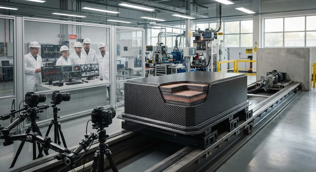
As electric vehicles proliferate across global markets, the battery enclosure has emerged as one of the most critical structural components in EV architecture. The enclosure must protect the battery modules from external impacts during collisions, maintain structural integrity under cra
Introduction
As electric vehicles proliferate across global markets, the battery enclosure has emerged as one of the most critical structural components in EV architecture. The enclosure must protect the battery modules from external impacts during collisions, maintain structural integrity under crash loads, shield electromagnetic interference from sensitive battery management systems, and contribute to overall vehicle lightweighting for extended range. Carbon fiber composite enclosures address all these requirements simultaneously, offering a compelling alternative to traditional steel and aluminum solutions.
Modern EV platforms demand battery enclosures that can withstand frontal, side, and rear impacts while maintaining the battery pack's structural integrity and preventing thermal runaway events. Carbon fiber's exceptional specific strength and energy absorption characteristics make it uniquely suited for this application. A typical carbon fiber battery enclosure saves 30-40% weight compared to aluminum equivalents while providing superior crash energy management through progressive crushing and controlled delamination mechanisms.
Crash Safety Standards and Requirements
Battery enclosures in electric vehicles must comply with multiple international safety standards that define crash performance requirements. The primary standards governing battery enclosure design include:
- UN ECE R100: Establishes requirements for electric vehicle safety, including battery enclosure crashworthiness and electrical isolation during and after impact.
- FMVSS 305: US standard requiring electrolyte containment, electrical isolation, and protection of the battery pack during frontal and side impacts.
- GB 38031-2020: Chinese standard specifying battery enclosure crash requirements, including no-fire and no-explosion criteria under specified impact conditions.
- EUCAR hazard levels: Defines the acceptable damage states for battery enclosures, from Level 0 (no damage) to Level 7 (fire or explosion).
These standards require the battery enclosure to maintain structural integrity during impact, prevent penetration of objects into the battery compartment, contain any electrolyte leakage, and maintain electrical isolation between the battery pack and the vehicle chassis. Carbon fiber enclosures must demonstrate compliance through standardized crash tests, including frontal barrier impacts, side pole impacts, and undercarriage strikes.
Carbon Fiber Enclosure Structural Design
A carbon fiber battery enclosure is typically designed as a multi-layer sandwich structure optimized for both crash energy management and electromagnetic shielding. The table below compares key design parameters across different enclosure architectures:
| Design Parameter | Steel Enclosure | Aluminum Enclosure | Carbon Fiber Enclosure |
|---|---|---|---|
| Weight (typical 60 kWh pack) | 85-95 kg | 55-65 kg | 35-45 kg |
| Specific energy absorption | 15-25 kJ/kg | 20-35 kJ/kg | 40-80 kJ/kg |
| Crush stroke efficiency | 60-70% | 65-75% | 75-85% |
| Electromagnetic shielding | Inherent (high conductivity) | Inherent (high conductivity) | Requires integrated mesh |
| Corrosion resistance | Poor (requires coating) | Moderate | Excellent |
| Tooling cost | Low | Medium | High (amortized at volume) |
The carbon fiber enclosure architecture typically comprises an outer structural shell, an inner containment liner, and integrated energy-absorbing crush zones. The outer shell uses carbon fiber/epoxy laminate with fiber orientations optimized for the expected crash load paths — typically a combination of 0°, ±45°, and 90° plies to handle both in-plane and oblique loading. The inner liner, often a thinner thermoplastic or metal foil layer, provides electrolyte containment and additional electromagnetic shielding.
Crash Energy Management Strategies
Carbon fiber's crash energy management relies on controlled progressive crushing rather than plastic deformation as in metals. The energy absorption mechanism involves a combination of fiber fracture, matrix cracking, delamination, and friction, which collectively absorb kinetic energy through material fragmentation. Design strategies to optimize crash performance include:
- Crush triggers: Geometric features (chamfers, notches, or thickness reductions) at the leading edge of crush zones initiate progressive crushing at controlled locations, preventing catastrophic global buckling.
- Fiber orientation optimization: Balancing 0° plies for axial load carrying with ±45° plies for shear resistance and 90° plies for transverse strength ensures stable crushing behavior across different impact angles.
- Hybridization: Incorporating glass fiber or aramid layers at crush initiation zones can improve crushing stability and reduce the sensitivity to impact angle variations.
- Internal energy-absorbing structures: Crushable tubes, honeycomb cores, or foam inserts within the enclosure absorb additional energy and prevent battery module intrusion.
Finite element analysis using explicit dynamics codes (LS-DYNA, PAM-CRASH) is essential for predicting crash behavior, as carbon fiber's progressive crushing involves complex failure modes that cannot be captured by simplified analytical methods. Material models incorporating strain-rate effects, damage evolution, and element deletion accurately simulate the crush process and enable optimization of the enclosure design before physical testing.
Electromagnetic Shielding Integration
While carbon fiber composites offer structural advantages, their electrical conductivity is significantly lower than metals — typically 1,000-10,000 S/m compared to aluminum's 37×10⁶ S/m. This lower conductivity means carbon fiber enclosures require explicit electromagnetic shielding to protect the battery management system (BMS) and other electronic components from external electromagnetic interference (EMI) and to prevent the enclosure itself from radiating EMI.
The shielding approach typically involves integrating a conductive mesh or foil within the composite layup:
- Expanded metal mesh: Aluminum or copper expanded foil (typically 20-50 g/m²) co-cured within the laminate provides broadband EMI shielding across the frequency range relevant to automotive electronics (150 kHz to 1 GHz).
- Metallic foil layers: Thin aluminum or copper foil (25-50 μm) bonded between composite plies offers high shielding effectiveness with minimal weight penalty.
- Conductive coatings: Spray-applied conductive coatings (nickel-filled epoxies, silver-filled silicones) on interior surfaces provide shielding where integrated mesh is impractical.
- Hybrid approaches: Combining mesh in structural panels with foil at joints and penetrations ensures continuous shielding coverage across the entire enclosure.
Shielding effectiveness is measured in decibels (dB) and must typically exceed 20-30 dB across the relevant frequency range for automotive EMC compliance. The combination of carbon fiber's inherent (moderate) conductivity with integrated metallic shielding elements achieves shielding levels comparable to solid metal enclosures while maintaining the weight advantage of composite construction.
Manufacturing and Quality Considerations
Carbon fiber battery enclosures are manufactured using several processes, each with specific advantages for different production volumes and performance requirements:
- Autoclave-cured prepreg: Highest quality and fiber volume fraction (55-60%), suitable for premium vehicles and low-to-medium volumes. Well-established process with extensive aerospace heritage.
- Out-of-autoclave (OoA) prepreg: Vacuum-bag-only curing at lower pressures (2-3 bar) reduces capital investment while maintaining good quality. Suitable for medium-to-high volumes.
- Resin transfer molding (RTM): Dry fiber preforms infused with resin in closed molds offer high production rates (cycle times under 10 minutes) and excellent surface finish. Ideal for high-volume automotive applications.
- Sheet molding compound (SMC): Chopped carbon fiber in thermoset or thermoplastic matrices, compression molded at high pressure, offers the highest production rates but lower mechanical properties than continuous fiber composites.
Quality control for battery enclosures includes non-destructive inspection (ultrasonic, X-ray) to verify bond quality and detect delaminations, dimensional inspection to ensure battery module fit, and electrical continuity testing to verify electromagnetic shielding integrity. Each enclosure must be individually tested for shielding effectiveness before assembly into the battery pack.
Frequently Asked Questions
How much weight does a carbon fiber battery enclosure save compared to aluminum?
A carbon fiber battery enclosure typically saves 30-40% weight compared to an equivalent aluminum enclosure. For a typical 60 kWh battery pack, this translates to a saving of 20-25 kg, which directly improves vehicle range by approximately 10-15 km per charge cycle. The weight saving is achieved through carbon fiber's higher specific strength and stiffness, allowing thinner wall sections while maintaining equivalent crash performance.
Does a carbon fiber battery enclosure meet crash safety standards?
Yes, carbon fiber battery enclosures are designed to meet or exceed all applicable crash safety standards, including UN ECE R100, FMVSS 305, and GB 38031-2020. Carbon fiber's high specific energy absorption (40-80 kJ/kg vs. 15-35 kJ/kg for metals) actually provides superior crash energy management, provided the enclosure is designed with appropriate crush zones and progressive crushing mechanisms. Physical crash testing and simulation validate compliance with all required standards.
How is electromagnetic shielding achieved in carbon fiber enclosures?
Carbon fiber's lower electrical conductivity compared to metals requires integrated electromagnetic shielding elements. The standard approach is incorporating expanded metal mesh (aluminum or copper, 20-50 g/m²) or thin metallic foil (25-50 μm) within the composite layup. This combination provides shielding effectiveness exceeding 20-30 dB across the automotive EMC frequency range, equivalent to solid metal enclosures while maintaining the weight advantage of composite construction.
What manufacturing processes are used for carbon fiber battery enclosures?
The primary manufacturing processes are autoclave-cured prepreg (highest quality, low-medium volumes), out-of-autoclave prepreg (vacuum bag only, medium-high volumes), resin transfer molding (RTM, high volumes with cycle times under 10 minutes), and sheet molding compound (SMC, highest volumes with compression molding). Process selection depends on production volume, performance requirements, and cost targets.
Conclusion
Carbon fiber battery enclosures represent a significant advancement in electric vehicle structural design, offering 30-40% weight savings over aluminum while providing superior crash energy management through progressive crushing mechanisms. The integration of electromagnetic shielding elements within the composite layup ensures protection of sensitive battery management electronics without compromising the weight advantage. As EV production volumes increase and manufacturing processes mature, carbon fiber enclosures will become increasingly competitive with metal solutions on both performance and cost metrics.
For EV manufacturers and battery pack integrators, carbon fiber enclosures offer a proven path to meeting stringent crash safety standards while achieving the lightweighting targets essential for extended vehicle range. Explore our carbon fiber product range or contact our engineering team to discuss material systems for your battery enclosure program.
Part of topic
Related Articles
- Carbon Fiber Mooring for Floating Offshore Wind: Fatigue and Corrosion in Deep Water
- Carbon Fiber Bicycle Frame Optimization: Layup Design and Manufacturing for Competitive Racing
- Carbon Fiber CFRP Retrofit for Infrastructure: Bridge and Building Seismic Strengthening
- Carbon Fiber Medical Imaging Equipment: Lightweight Gantry and Couch Structures for MRI/CT
- Carbon Fiber Structures for Low-Altitude Economy: UAV Airframes and eVTOL Components
- Carbon Fiber Satellite Structures: Dimensional Stability for Space Environment Cycling
Interested in Our Products?
Contact our team for competitive pricing and technical specifications.
Get a QuoteRelated Products

Carbon Fiber Plate — 3K Twill T700 1.5mm
Thin 1.5mm carbon fiber plate with 3K twill weave surface. Lightweight and stiff, commonly used for covers, panels, drone bodies, and applications requiring a premium aesthetic appearance.

Carbon Fiber Plate — 3K Twill T700 3.0mm
Medium-thickness 3.0mm carbon fiber plate offering significantly higher load capacity while maintaining attractive 3K twill finish. Suitable for structural brackets, reinforcement plates, and load-bearing panels.

Square Carbon Fiber Tube — 3K Twill T700
Square cross-section carbon fiber tube manufactured with 3K twill weave for torsional strength. Preferred for structural frames, trusses, and support columns where rectangular geometry offers design flexibility.

Carbon Fiber Plate — UD Unidirectional T700
Unidirectional carbon fiber plate with all fibers oriented in a single direction for maximum strength along the fiber axis. Essential for structural reinforcements, splints, and applications where load direction is predictable.

Round Carbon Fiber Tube — UD Unidirectional T700
Unidirectional (UD) round tube with all fibers aligned axially for maximum longitudinal stiffness. Ideal for applications requiring high bending rigidity with minimal weight, such as shafts, struts, and structural reinforcements.