
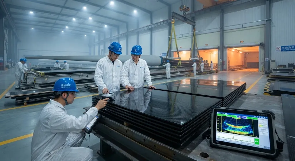
In May 2026 a 107-meter offshore wind blade left a production facility in Fujian, China, bound for a 12-16 MW turbine platform. It is the longest commercial blade manufactured to date, and each unit contains more than eight tonnes of carbon fiber concentrated almost entirely in the spar
Introduction
In May 2026 a 107-meter offshore wind blade left a production facility in Fujian, China, bound for a 12-16 MW turbine platform. It is the longest commercial blade manufactured to date, and each unit contains more than eight tonnes of carbon fiber concentrated almost entirely in the spar caps. The blade is not a marginal step in scale; it crosses a threshold where glass fiber alone can no longer carry the gravity loads and fatigue demands of a 100-meter-plus rotor, which is why carbon fiber content in offshore blades has become the single largest growth channel for industrial-grade carbon fiber.
This article breaks down the engineering logic of carbon spar caps in megawatt-scale offshore blades: why carbon is structurally required at this length, how spar caps are designed and laid up, how pultrusion and infusion manufacturing keep cost under control, and how the 107-meter class changes the demand picture for large-tow carbon fiber. The goal is to give composite engineers and procurement teams a working reference for assessing spar cap materials, suppliers, and manufacturing routes.
Why Carbon Spar Caps Become Mandatory Beyond 90 Meters
A wind blade spar cap resists the flapwise bending moment generated by aerodynamic lift. As blade length grows, the bending moment scales faster than the blade weight, and the gravity-induced alternating load at the blade root becomes the critical fatigue case. For blades up to roughly 60-70 meters, high-modulus glass fiber caps are adequate. Above that range blade designers face three compounding problems with glass:
- Self-weight penalty: Glass fiber has a density around 2.1 g/cm³ compared with 1.8 g/cm³ for carbon, and its lower fatigue endurance forces thicker caps that add still more weight to the root bending moment.
- Fatigue erosion: The alternating gravity load at 10-15 revolutions per minute creates billions of cycles over a 25-year design life; glass retains a smaller fraction of its static strength under these high-cycle loads than carbon does.
- Tip deflection amplification: A soft, heavy glass cap allows larger tip deflection, increasing tower clearance requirements and the risk of blade-tower impact in extreme events, forcing a stiffer overall structure that weighs even more.
Carbon spar caps solve all three at once: higher modulus (230-295 GPa versus 85-95 GPa for high-modulus glass), lower density, and superior fatigue retention. On the 107-meter class, carbon caps reduce blade mass by roughly 20-30% and cut the gravity-driven root moment enough to bring the blade within the design envelope of existing offshore drivetrains.
Spar Cap Architecture and Design Drivers
The spar cap is the laminate stack that runs along the blade length at the maximum chordwise thickness, bonded to the shear webs. For the 107-meter class the cap accounts for about 60-70% of the blade's carbon fiber content. Three design decisions dominate:
- Fiber orientation: Caps are essentially unidirectional, with 0° fibers aligned with the blade axis. Off-axis plies (typically 5-10% of the stack) protect against transverse cracking and handle the biaxial load at the cap-web junction.
- Thickness tapering: The cap is thickest at the root — often 100-150 mm of consolidated laminate — and thins toward the tip. Pultruded plates allow precise ply-drop scheduling, so thickness follows the bending moment envelope closely instead of in discrete steps.
- Material grade selection: Standard-modulus carbon (T700-class, 230 GPa) dominates pultruded caps for cost reasons; intermediate-modulus fiber (T800-class, around 295 GPa) appears where the blade design seeks stiffer tips without adding plate thickness, typically in the outboard 20-30% of the cap.
The comparison below summarizes the material options for large offshore spar caps:
| Material | Tensile modulus (GPa) | Density (g/cm³) | Fatigue performance | Relative cost |
|---|---|---|---|---|
| High-modulus glass (H-glass) | 85-95 | 2.1 | Moderate, steep S-N slope | Lowest |
| Standard-modulus carbon (T700-class) | 230 | 1.8 | Excellent flat S-N curve | Medium |
| Intermediate-modulus carbon (T800-class) | 290-300 | 1.8 | Excellent, higher static strength | High |
| Hybrid carbon-glass cap | 120-180 | 1.9-2.0 | Good, transitional | Low-medium |
In practice most 100-meter-class blades use a pure carbon pultruded cap with a short glass transition zone at the blade root to manage the load introduction into the bolted root insert region, where transverse properties and compressive stability matter more than axial stiffness.
Manufacturing Routes: Pultrusion and Panel Bonding
Two manufacturing routes dominate spar cap production, and the choice drives both mechanical consistency and cost.
- Pultruded plates: Unidirectional carbon fiber or prepreg tow is pulled through a heated die to form continuous plates 200-400 mm wide and 2-6 mm thick. The plates are cut to length, stacked to the target thickness, and bonded into the blade skin during infusion. Pultrusion achieves fiber volume fractions of 60-70% with excellent void control (below 1%), and the process runs at 0.5-2 m/min, producing tens of tonnes of cap material per line per year.
- Direct prepreg layup: Unidirectional prepreg is cut and laid directly into the cap mold by laser-guided or AFP (automated fiber placement) systems. AFP allows variable thickness and steered fiber paths but is slower and more expensive; it is chosen for the outboard cap sections where taper scheduling is complex.
Quality assurance for pultruded plates is built around ultrasonic scanning of the consolidated stack and mechanical testing of witness coupons per production batch. Acceptance criteria typically include fiber volume fraction by acid digestion, void content by microscopy, and a minimum compressive strength parallel to the fiber direction, since the cap ultimately fails in compression on the windward side under extreme gusts.
Why the Pipeline Economics Matter
The 107-meter blade does more than set a size record; it re-shapes the carbon fiber demand curve for wind. A single 20 MW-class turbine with three 107-meter blades consumes roughly 24-30 tonnes of carbon fiber. A 1 GW offshore wind farm at 16 MW per turbine needs about 60-70 turbines, translating to 1,500-2,000 tonnes of carbon fiber per gigawatt — before accounting for scrap and process losses, which add another 10-15%. This is the scale that justifies new large-tow production lines: 48K and 60K tow, which lower unit cost dramatically compared with aerospace-grade 12K and 24K material.
For blade manufacturers and project developers, the practical takeaway is that carbon fiber supply agreements for megawatt-scale offshore platforms now need to be negotiated at the gigawatt-project horizon, with grade specifications fixed early. Pultruded plate capacity is the bottleneck to watch, because lead times for new pultrusion lines run 12-18 months, and the 2026 order book already exceeds available capacity in several regions.
Frequently Asked Questions
Why is carbon fiber used in spar caps and not in the whole blade?
Carbon fiber is used selectively because it is expensive and anisotropic. The spar cap carries the dominant flapwise bending load, so placing unidirectional carbon exactly there maximizes stiffness and fatigue benefit per kilogram. The blade skins, shear webs, and trailing edge carry lower loads and are made from glass fiber composites or sandwich materials, which are cheaper and lighter for those load cases. This hybrid architecture concentrates carbon where it pays, keeping blade cost per kilowatt competitive while enabling lengths beyond 90 meters.
How much lighter is a 107-meter carbon spar cap blade compared with an all-glass design?
A well-designed carbon-capped blade is typically 20-30% lighter than an equivalent all-glass blade at the same length. More importantly, the reduction in the gravity-driven root bending moment is larger than the mass saving alone, because removing mass from the outboard blade reduces the alternating load that drives fatigue. On the 107-meter class, carbon caps avoid what would otherwise be an unbuildable glass blade: structural weight would push root loads and tip deflection beyond the design envelope of the turbine and tower.
What is the risk of using standard-modulus rather than intermediate-modulus carbon in offshore spar caps?
Standard-modulus fiber (T700-class, 230 GPa) has a 20-25% lower stiffness than intermediate-modulus fiber, so the cap must be thicker to reach the same global blade stiffness and tip deflection target. That extra thickness increases weight and cost per blade but remains cheaper than paying for IM fiber across the entire cap. The primary risks are ply-drop complexity and the need for careful structural bonding when stacking many pultruded plates. IM carbon (T800-class) is reserved for the outboard cap, where a stiffer tip reduces tip deflection under extreme gusts and cuts tower clearance risk with minimal added mass.
Conclusion
The 107-meter offshore blade marks the point where carbon fiber spar caps move from an optimization option to a structural requirement. At 12-16 MW scale, glass caps cannot economically meet the gravity-driven fatigue and tip deflection limits, and carbon delivers the 20-30% mass reduction and the flat S-N behavior that make 100-meter-plus rotors feasible. The manufacturing story is equally important: pultruded large-tow plates keep cost competitive while delivering the void-free, fiber-volume-consistent material that offshore certification demands.
For teams planning offshore blade programs or carbon spar cap supply agreements, the key questions are grade selection (standard versus intermediate modulus), pultrusion capacity availability, and testing infrastructure for fatigue qualification. Explore our carbon fiber unidirectional and pultrusion-oriented product range, or contact our engineering team to discuss spar cap material selection and supply planning for your blade program.
Part of topic
Related Articles
- Carbon Fiber Mooring for Floating Offshore Wind: Fatigue and Corrosion in Deep Water
- Carbon Fiber Bicycle Frame Optimization: Layup Design and Manufacturing for Competitive Racing
- Carbon Fiber CFRP Retrofit for Infrastructure: Bridge and Building Seismic Strengthening
- Carbon Fiber Medical Imaging Equipment: Lightweight Gantry and Couch Structures for MRI/CT
- Carbon Fiber EV Battery Enclosures: Crash Safety and Electromagnetic Shielding Design
- Carbon Fiber Structures for Low-Altitude Economy: UAV Airframes and eVTOL Components
Interested in Our Products?
Contact our team for competitive pricing and technical specifications.
Get a QuoteRelated Products

Carbon Fiber Plate — 3K Twill T700 3.0mm
Medium-thickness 3.0mm carbon fiber plate offering significantly higher load capacity while maintaining attractive 3K twill finish. Suitable for structural brackets, reinforcement plates, and load-bearing panels.

Carbon Fiber Plate — 3K Twill T700 1.5mm
Thin 1.5mm carbon fiber plate with 3K twill weave surface. Lightweight and stiff, commonly used for covers, panels, drone bodies, and applications requiring a premium aesthetic appearance.

Square Carbon Fiber Tube — 3K Twill T700
Square cross-section carbon fiber tube manufactured with 3K twill weave for torsional strength. Preferred for structural frames, trusses, and support columns where rectangular geometry offers design flexibility.

Carbon Fiber Plate — UD Unidirectional T700
Unidirectional carbon fiber plate with all fibers oriented in a single direction for maximum strength along the fiber axis. Essential for structural reinforcements, splints, and applications where load direction is predictable.

Round Carbon Fiber Tube — UD Unidirectional T700
Unidirectional (UD) round tube with all fibers aligned axially for maximum longitudinal stiffness. Ideal for applications requiring high bending rigidity with minimal weight, such as shafts, struts, and structural reinforcements.