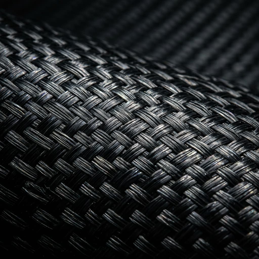

Building or repairing carbon fiber tubes for rc planes starts with the load path, not the catalog. The outer diameter that works as a wing spar on a park flyer will fail as a tail boom on a 2.5 m glider, because what the airframe actually consumes is bending stiffness, hoop integrity at the mounts,
Introduction
Building or repairing carbon fiber tubes for rc planes starts with the load path, not the catalog. The outer diameter that works as a wing spar on a park flyer will fail as a tail boom on a 2.5 m glider, because what the airframe actually consumes is bending stiffness, hoop integrity at the mounts, and enough wall thickness to survive one bad landing. This article works through the three places where tubes do real work on a model aircraft, gives sizing bands for common diameters, compares tubes against solid rods, and closes with bonding and inspection rules that keep a build flying after a hard season.
Treat every number here as a working band for standard-modulus fiber in epoxy, then confirm it against your own model: all-up weight, wing loading, expected gust load and how the mounts are drilled all shift the answer. The goal is a tube that stays straight after a full season, not one that passes a bench flex test.
Carbon Fiber Tubes for RC Planes: Where Each Tube Goes
The wing spar carries the bending moment from root to tip, and it is the one tube where stiffness per gram decides flight time. A round tube resists bending equally in every plane and tolerates the point loads of a joiner sleeve, which is why most kits use a single inner tube or a pair of outer tubes instead of a flat strip. The tail boom does a different job: it holds the stabilizer far behind the center of gravity while damping the fin flutter that a too-soft boom will amplify at speed, so boom choice is about length-to-diameter ratio and joint stiffness rather than raw strength. Frame members — battery rails, servo trays, landing-gear sleeves — mostly need crush resistance and a straight bonding surface, and that is where thinner walls and smaller diameters save weight nobody will notice.
- Wing spar: largest diameter the airfoil allows, wall sized for root bending, plus a joiner sleeve that spreads point load.
- Tail boom: long, thin-walled, diameter stepped up at the fin mount where the moment peaks.
- Battery rails and trays: small stiff tubes bonded to formers, sized for crush and mounting screws rather than bending.
- Landing-gear sleeves: short thick-walled sections that take impact and abrasion, often replaced after a season.
Carbon Fiber Tubes for RC Planes: Diameters, Walls and Stiffness Bands
Tube stiffness scales with the fourth power of diameter for a given wall, so a 16 mm tube is not merely twice as stiff as an 8 mm one, while mass grows only with the circumference. That asymmetry is why stepping diameter up one size and wall down slightly almost always beats adding wall at a small diameter. The table below lists common positions with working bands; confirm the actual inside diameter against your joiners, sleeves and hardware before ordering, because millimeter-scale differences decide whether a part slips or binds.
| Position | Outside diameter | Wall | Notes |
|---|---|---|---|
| Park flyer wing spar | 6 to 8 mm | 0.5 to 0.8 mm | Inner-tube joiner, sub-2 kg all-up |
| Glider wing spar, 1.5 to 2.5 m | 10 to 16 mm | 0.8 to 1.5 mm | Outer-tube pair or single heavy inner |
| Pusher or pylon tail boom | 14 to 30 mm | 0.6 to 1.2 mm | Step up diameter at the fin mount |
| Battery rail, fuselage stringer | 6 to 12 mm | 0.4 to 0.7 mm | Crush and screw retention dominate |
| Landing-gear sleeve | 8 to 14 mm | 1.0 to 2.0 mm | Impact duty, replaceable |
Weight per meter matters less than it appears: the difference between a 0.5 mm and a 1.0 mm wall on a 10 mm tube is about two grams per meter, while the stiffness change is close to a factor of two. Spend grams where the load curve peaks — the root end of a spar and the base of a boom — and save them at the tips where the moment falls away.
Carbon Fiber Rods for RC Planes versus Round Tubes
Where a part is thin, sees point loads or must pass through a tight bend, a solid rod wins: control linkages, wingtips, antenna masts and joiner pins all want the crush and buckling resistance that only a solid section gives. A carbon fiber rod 1mm is the standard choice for short control runs on small models, and carbon fiber rods for rc planes are cheaper to stock than matched tubes because no sleeve or glue gap is involved. Tubes win wherever bending stiffness per gram is the whole question — spars, booms and stringers — because the material sits at the radius where it does the most work instead of crowding the neutral axis.
The practical rule is simple: if the part transfers a distributed bending load, use a tube; if it takes a concentrated push, pull or impact, use a rod. Landing gear is the usual exception, where a rod inside a tube gives a damped, springy leg that survives arrivals a pure tube would crack on. When both options fit, compare stiffness at equal weight rather than at equal diameter, and the right answer usually shows up in one line of arithmetic.
Mounting, Bonding and Crash Replacement
Bonded joints hold tubes together better than clamped ones, provided the surface is prepared. Sand the glue zone with coarse paper, wipe with alcohol, and scuff the inside of any sleeve; epoxy fillets then carry load across the full overlap instead of at two hard points. Drill through tubes with a backing block and moderate speed to avoid exit breakout, and never overtighten a clamp against a thin wall, because the crush ring that results will hide under the wrap until the first hard maneuver finds it.
After any hard landing, inspect before flying again: rotate the model and sight along each spar and the boom for a smooth line, press the finish around the mounts for soft spots that signal delamination, and check the joiner sleeve for a shifted seam. A tube that shows a crease, a paint crack that opens when flexed, or a mount that no longer sits flush has finished its service life — retired tubes make excellent replacements for battery rails and trays, where the loads are lower and the bent spar will never be missed.
Frequently Asked Questions
How do I size a wing spar tube for a new design?
Start from the root bending moment at maximum lift plus a landing factor, then pick the largest diameter your airfoil section allows and solve for wall thickness against that moment with a safety margin of roughly 1.5. Check the deflection limit too: a spar that is strong but soft will wash out in a pull-up and change the trim mid-flight. If the numbers land between two standard sizes, take the larger diameter with the thinner wall and verify the joiner sleeve still fits the inside diameter before you order.
Should I use tubes or rods for a pylon-style tail boom?
Use a tube. A boom works in bending and needs stiffness along its whole length, which is exactly the load case where a hollow section beats a solid one at equal weight; a rod of equivalent stiffness would be heavier than the entire airframe can afford. Size the boom diameter at the fin mount first, since that is where the moment peaks, and step the wall down toward the fuselage end where the section is supported on both sides. If the boom must also carry wiring, confirm the inside diameter leaves room for the loom without rubbing through the insulation.
When should I retire a crashed tube instead of repairing it?
Retire any spar or boom with a crease, a delaminated area that flexes under thumb pressure, or a crack that opens when the section is bent by hand; these failures are progressive, and a repair that restores stiffness by adding wrap also adds mass you did not budget for. Cosmetic chips in the finish can be sanded and sealed without drama, and landing-gear sleeves are cheap enough to treat as consumables. When in doubt, demote the part: a spar that failed the crash inspection becomes a battery rail, and the new spar takes its place before the next flight.
What wall thickness should a carbon fiber boom have?
Between 0.6 and 1.2 mm covers most model booms, with the wall set by the fin mount moment rather than by the tube middle; thin walls save weight but dent in a bag, so go thicker if the boom is handled roughly. Confirm the wall against your mounting hardware as well, because a screw that nearly breaches a 0.6 mm wall will not hold threads after the second removal. If the boom also serves as a conduit, line the inside with a light sleeve where cables pass clamps.
Conclusion
Sizing carbon fiber tubes for RC planes is a stiffness problem dressed as a parts order: identify where each tube works, step diameter before wall, and reserve grams for the root and the fin mount rather than the tips. Rods stay in their lane for point loads and linkages, tubes take the distributed bending, and both deserve the same post-crash inspection before the next flight.
Start with the load path and the mounting hardware, then match diameter and wall to the bands above. Browse our carbon fiber tube range or send us your model specifications and we will help match a tube to the load case instead of the closest shelf size.
Part of topic
Related Articles
- Carbon Fiber Drone: When Composite Airframes Make Sense
- Carbon Fiber Rod Fishing: Blank Grades and Action Curves Explained
- Carbon Fiber Tube Protector: Edge Guards and Damage Prevention
- Carbon Fiber RC Body: Lightweight Shells for On-Road and Off-Road Cars
- Carbon Fiber FPV Drone Frame: Geometry, Materials and DIY Builds
- Pultruded Carbon-Fiber Leaf Springs: Composite Suspension for Commercial Vehicles
Interested in Our Products?
Contact our team for competitive pricing and technical specifications.
Get a QuoteRelated Products
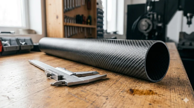
Round Carbon Fiber Tube — 3K Plain Weave T700
Standard round carbon fiber tube manufactured from Toray T700 grade fiber with 3K plain weave. Offers balanced strength and stiffness for general industrial applications including robotics, automation, sports equipment, and aerospace structures.
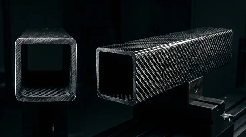
Square Carbon Fiber Tube — 3K Twill T700
Square cross-section carbon fiber tube manufactured with 3K twill weave for torsional strength. Preferred for structural frames, trusses, and support columns where rectangular geometry offers design flexibility.
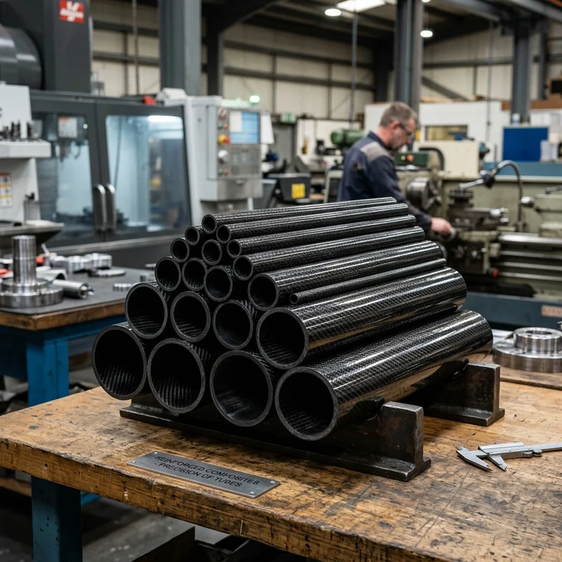
Round Carbon Fiber Tube — 3K Twill
Lightweight and ultra-stiff round tubes ideal for drone frames, robotics, and structural applications.
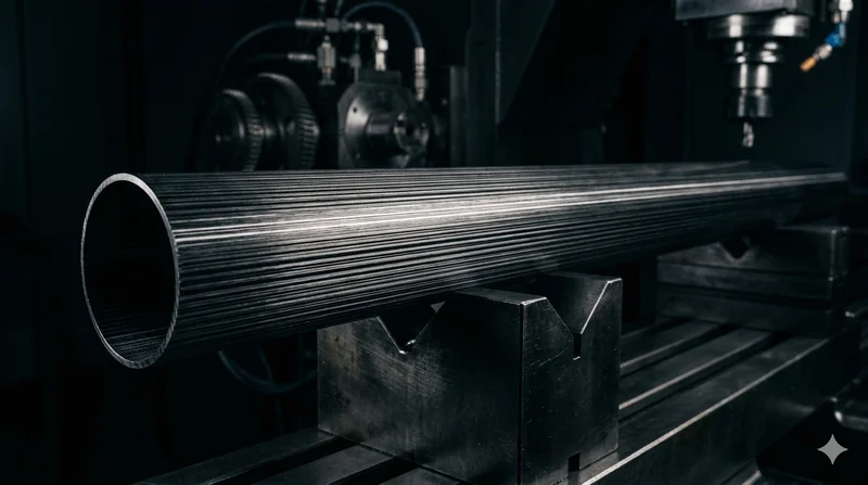
Round Carbon Fiber Tube — UD Unidirectional T700
Unidirectional (UD) round tube with all fibers aligned axially for maximum longitudinal stiffness. Ideal for applications requiring high bending rigidity with minimal weight, such as shafts, struts, and structural reinforcements.
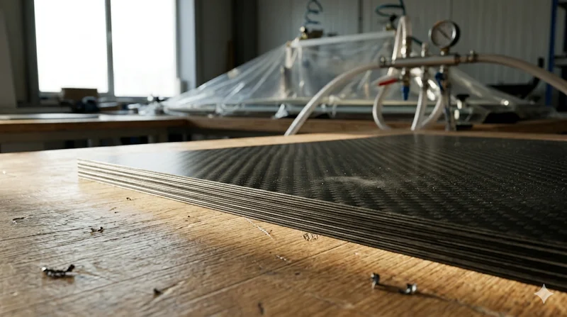
Carbon Fiber Plate — 3K Twill T700 3.0mm
Medium-thickness 3.0mm carbon fiber plate offering significantly higher load capacity while maintaining attractive 3K twill finish. Suitable for structural brackets, reinforcement plates, and load-bearing panels.