
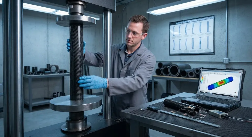
Carbon fiber tube strength is not a single number printed on a datasheet; it is a family of properties that change with load direction, tube geometry, winding architecture, and failure mode. A carbon fiber tube loaded in pure axial tension fails differently from the same tube under bending, and both
Introduction
Carbon fiber tube strength is not a single number printed on a datasheet; it is a family of properties that change with load direction, tube geometry, winding architecture, and failure mode. A carbon fiber tube loaded in pure axial tension fails differently from the same tube under bending, and both fail differently under torsion. When engineers ask about carbon fiber tube strength, they are usually asking one of three questions: how much axial or bending load the tube can carry, how to account for buckling on long slender tubes, and what safety factor to apply between test data and design use. This article answers all three, walking through carbon fiber tube strength analysis methods, a worked CFRP tube strength calculation, the load capacity limits that buckling and joints impose, and the composite tube structural verification that turns material data into a production-ready design.
Carbon Fiber Tube Strength Analysis: The Building Blocks
A meaningful carbon fiber tube strength analysis starts from the fiber and works up to the tube. The reinforcing fiber provides tensile strength and stiffness along its axis; the epoxy matrix transfers load between fibers, stabilizes them against buckling, and provides shear strength; and the winding or lamination architecture decides how those properties are distributed around the tube circumference. Three analysis layers follow:
- Lamina properties: The unidirectional ply properties — longitudinal and transverse modulus, tensile and compressive strength, and in-plane shear strength — form the input data. These come from coupon testing of the same fiber and resin system at the same fiber volume fraction.
- Layup analysis: Classical lamination theory combines the lamina properties with the stacking sequence to compute the tube wall's effective stiffness matrix, accounting for the fiber angle of each layer.
- Tube-level analysis: The wall stiffness feeds a beam or shell model of the full tube, which computes stress and strain under the applied axial, bending, torsional, and pressure loads.
The failure check then compares computed stresses against allowables at each ply level, because a tube wall rarely fails uniformly — the critical ply under a given load direction fails first, and the mode matters as much as the magnitude.
CFRP Tube Strength Calculation: A Worked Example
To make the method concrete, consider a round carbon fiber tube with an outer diameter of 40 mm, a wall thickness of 3 mm, and a quasi-isotropic layup of T700-grade carbon fiber in epoxy. The tube is loaded in pure axial compression. The relevant section properties are an area of about 349 mm², a moment of inertia of about 62,000 mm⁴, and a radius of gyration of roughly 13.3 mm. With a laminate compressive modulus of approximately 55 GPa and a compressive strength of about 480 MPa at 60 percent fiber volume fraction, the short-column axial load capacity works out to about 167 kN before material failure — if the tube is short enough to fail by crushing rather than buckling.
| Parameter | Value | Basis |
|---|---|---|
| Outer diameter | 40 mm | Design input |
| Wall thickness | 3 mm | Design input |
| Cross-sectional area | 349 mm² | Computed |
| Compressive modulus (laminate) | 55 GPa | Coupon data |
| Compressive strength (laminate) | 480 MPa | Coupon data |
| Short-column axial capacity | 167 kN | Strength times area |
| Euler buckling load at 1 m length | 53 kN | Euler buckling formula |
The striking result is that at a 1-meter length, the Euler buckling load of 53 kN is less than one third of the material strength limit. This is the defining feature of carbon fiber tube strength analysis: because carbon fiber composites are so strong in compression, slender tubes almost always fail by elastic buckling long before the material is stressed to its limit. Increasing the tube diameter, adding a sandwich wall, or shortening the column are the practical levers.
Carbon Fiber Tube Load Capacity: Buckling and Joint Limits
Once material strength is understood, two additional limits dominate carbon fiber tube load capacity in practice. The first is global and local buckling. Global Euler buckling governs long, unsupported columns and follows the classical Euler buckling formula, where the critical load scales with the axial modulus and moment of inertia and falls with the square of the unsupported length, but local buckling of the thin cylindrical wall can occur at lower loads on large-diameter thin-wall tubes, appearing as diamond-shaped wrinkles in the wall. Both depend strongly on the axial modulus, which is why high-modulus fibers change not just the stiffness but also the stability of a tube.
The second limit is the joint. A carbon fiber tube is only as strong as its end connection, and bonded, bolted, and clamp joints each impose their own load ceiling. Bonded joints transfer load through the adhesive's shear strength and typically fail by progressive peel at the tube end; bolted joints concentrate stress at fastener holes and are limited by bearing and net-section strength; clamp joints are limited by the friction and compressive capacity of the wall. Most tube failures in service begin at the joint, not in the mid-span, which is why composite tube structural verification always includes joint qualification testing alongside coupon testing.
Design Allowables and Verification
Design allowables for carbon fiber tubes convert measured data into safe design values through a disciplined sequence of reductions. The starting point is coupon test data from the actual fiber, resin, and fiber volume fraction. Environmental knockdown factors of 15-25 percent account for moisture and temperature effects, and scatter factors derived from the test population, such as a B-basis value where 90 percent of the population exceeds the allowable with 95 percent confidence, capture batch variability. A final safety factor of 1.5-2.0 for structural service, or 2.0-2.5 for pressure-critical or flight applications, brings the design value to its working level.
Verification completes the loop in three stages. Finite element analysis of the tube and its joints checks stress distribution and buckling modes before any hardware exists. Static testing of prototype tubes to failure validates the analysis on real specimens and confirms the failure mode and location match the prediction. Finally, quality control testing on production batches — burst, stiffness, and dimensional checks — confirms that the delivered tube matches the verified design. Engineers should insist on verification data that names the fiber grade, fiber volume fraction, and test standard, because these three details determine whether published carbon fiber tube strength values apply to their specific tube at all.
Frequently Asked Questions
How much load can a carbon fiber tube carry?
It depends on the diameter, wall thickness, fiber grade, layup, and especially the length. A 40 mm outer diameter tube with a 3 mm wall in a T700 quasi-isotropic layup carries roughly 167 kN in short-column axial compression, but only about 53 kN as a 1-meter-long column before Euler buckling — and less under bending or torsion. Rather than memorizing a number, run the section calculation with your dimensions and check the buckling load at your unsupported length, because for slender tubes buckling almost always governs.
What is the difference between carbon fiber tube strength and stiffness?
Strength is the maximum stress the tube can sustain before failure, measured in MPa; stiffness is the ratio of stress to strain, the modulus, measured in GPa, and it determines how much the tube deflects under load. The two are related but independent: a high-modulus fiber can make a tube stiff without necessarily raising its failure stress, because failure in compression is often governed by micro-buckling of the fibers rather than the intrinsic fiber strength. In design, stiffness governs deflection and buckling performance while strength governs the ultimate load, and both checks must pass.
Why do carbon fiber tubes fail by buckling before reaching their material strength?
Because carbon fiber composites have an unusually high strength-to-modulus ratio in compression. A material with high compressive strength but moderate modulus becomes structurally unstable at a lower load than the one that crushes it: the column bows sideways elastically, the thin cylindrical wall develops local wrinkles, and the load cannot be carried regardless of how strong the material is. This is why tube geometry — diameter, wall thickness, and unsupported length — is often more influential on load capacity than the fiber grade itself, and why long slender carbon fiber tubes need sandwich walls, ribs, or bracing to reach their material-limited capacity.
Conclusion
Carbon fiber tube strength is best understood as a system: lamina properties feed a layup analysis, the layup feeds a tube-level model, buckling and joint limits cap the usable load, and a disciplined sequence of environmental knockdowns and safety factors produces the design allowable. The worked CFRP tube strength calculation above shows why geometry and buckling dominate — a 40 mm tube that can crush at 167 kN buckles at just 53 kN over a 1-meter span — and why joint design deserves as much attention as the tube wall itself. With the right analysis and verification, composite tube structural design becomes a repeatable engineering process rather than a gamble on datasheet numbers.
When your project needs carbon fiber tubes with verified strength data and analysis support, review our carbon fiber tube and profile range or contact our engineering team with your tube dimensions, load case, and unsupported length, and we will help you run the strength and buckling checks for your application.
Part of topic
Related Articles
- Filament Wound Epoxy Tubes Advantages: Over Metal and Pultruded Alternatives
- Filament Wound Epoxy Tubes: Mechanical Properties and Material Data Sheets
- Carbon Fiber Drone Blades and Propellers: Stiffness, Balance and Noise Reduction
- Fiberglass Filament Wound Tubes: Cost-Effective Alternative to Carbon Fiber
- Filament Wound Epoxy Tube Design: Wall Thickness, Fiber Angle and Load Optimization
- Filament Wound Epoxy Tubes: Testing Standards and Quality Assurance
Interested in Our Products?
Contact our team for competitive pricing and technical specifications.
Get a QuoteRelated Products

Carbon Fiber Fishing Rod Blank
High-quality carbon fiber fishing rod blank manufactured from multiple grades of Toray carbon fiber cloth. Available in a wide range of lengths, powers, and actions for freshwater and saltwater applications. Suitable for OEM rod building.

Carbon Fiber Plate — 3K Twill T700 3.0mm
Medium-thickness 3.0mm carbon fiber plate offering significantly higher load capacity while maintaining attractive 3K twill finish. Suitable for structural brackets, reinforcement plates, and load-bearing panels.

Carbon Fiber Plate — 3K Twill T700 1.5mm
Thin 1.5mm carbon fiber plate with 3K twill weave surface. Lightweight and stiff, commonly used for covers, panels, drone bodies, and applications requiring a premium aesthetic appearance.

Square Carbon Fiber Tube — 3K Twill T700
Square cross-section carbon fiber tube manufactured with 3K twill weave for torsional strength. Preferred for structural frames, trusses, and support columns where rectangular geometry offers design flexibility.
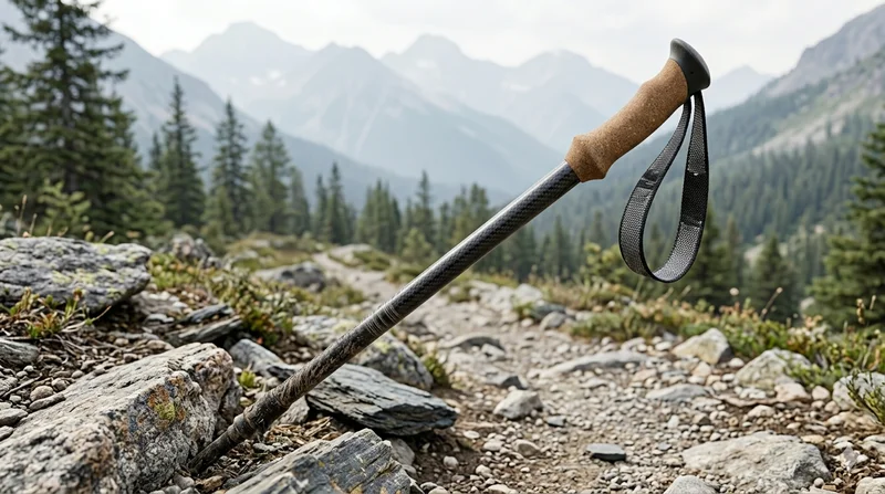
Carbon Fiber Trekking Pole
Lightweight carbon fiber trekking pole manufactured from high-grade carbon fiber tube. Weighs only 160g per pole while providing superior shock absorption and durability for hiking, trail running, and backpacking.