
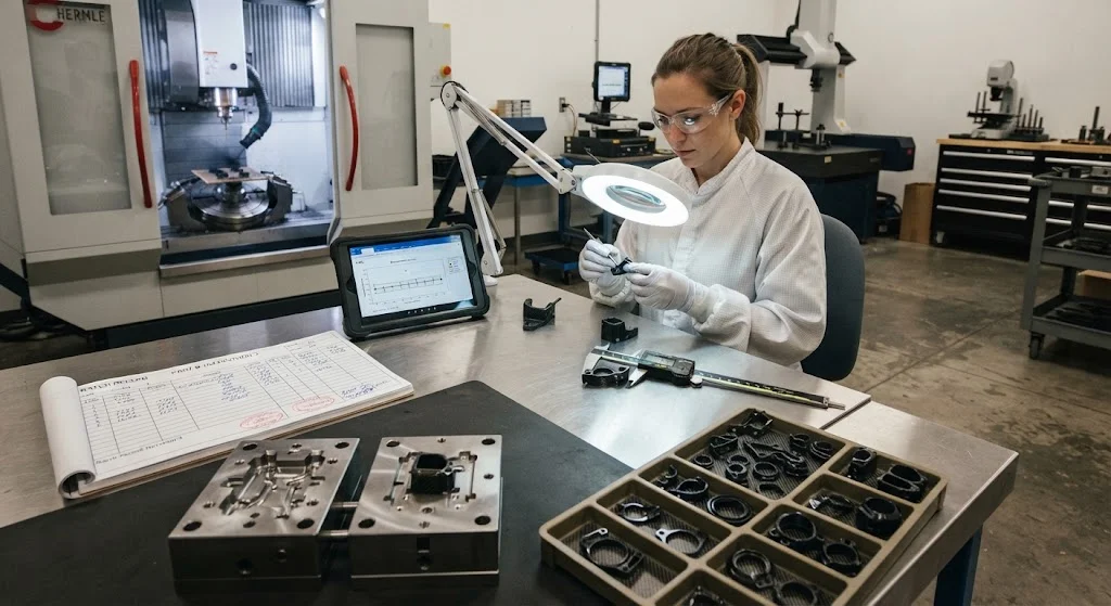
Carbon fiber small parts have become the default engineering choice in high-end electronics and medical devices, where low mass, dimensional stability, and fatigue resistance matter more than raw material cost. From drone camera gimbals and robotic end-effector fingers to surgical instrument handles
Introduction
Carbon fiber small parts have become the default engineering choice in high-end electronics and medical devices, where low mass, dimensional stability, and fatigue resistance matter more than raw material cost. From drone camera gimbals and robotic end-effector fingers to surgical instrument handles and imaging-system brackets, these small CFRP components replace machined aluminum and steel because they cut component weight by 40-60 percent while delivering stiffness-to-weight ratios that metal cannot match. Precision carbon fiber parts demand a different manufacturing discipline than large composite structures: tolerances shrink to ±0.05 mm, wall sections drop below 1 mm, and setup and tooling economics dominate every sourcing decision. This article explains how precision carbon fiber parts are designed and manufactured for electronics and medical applications, what tolerance levels are realistically achievable, and how quality is verified in series production.
For engineers, the practical question is not whether carbon fiber outperforms metal — it does — but whether a small part can be made to the required tolerance at an acceptable cost. The answer depends on material form, molding method, tooling design, and inspection strategy, and each of these interacts with the others. This guide gives you the vocabulary and the acceptance criteria to specify carbon fiber small parts with confidence.
Why Carbon Fiber Small Parts Replace Metal in Electronics and Medical Devices
In small-format components, the performance gap between carbon fiber and metal is widest exactly where electronics and medical devices are most demanding. The table below summarizes the key property comparison for small-part design.
| Property | Carbon fiber (CFRP) | Aluminum 6061 | Titanium Ti-6Al-4V |
|---|---|---|---|
| Density | 1.5-1.6 g/cm³ | 2.7 g/cm³ | 4.4 g/cm³ |
| Specific stiffness | 25-35 (high modulus) | 26 | 25 |
| Fatigue endurance | 60-70% of static strength | 30-40% | 50-60% |
| CTE (axial, high modulus) | 0 to -1 ppm/°C | 23 ppm/°C | 9 ppm/°C |
| Vibration damping | 4-6 times aluminum | 1 (baseline) | 1.5 |
Three properties drive most design decisions. First, the combination of low density and high specific stiffness enables mass reductions that matter for wearable devices, surgical instruments held for hours, and moving payloads on robots and drones. Second, the near-zero coefficient of thermal expansion of high-modulus carbon fiber keeps precision optics and sensor mounts dimensionally stable across operating temperature ranges — a property that aluminum and titanium simply do not have. Third, the high damping ratio of carbon fiber suppresses vibration in handheld instruments and precision positioning stages, improving image quality in endoscopes and stabilizing camera gimbals in flight.
Precision Carbon Fiber Parts: Manufacturing Methods Compared
Small composite parts are produced by a narrower set of processes than large structures, and the choice of process fixes the achievable tolerance, cost, and production rate. Four methods dominate small-part production.
- Compression molding with chopped carbon fiber compound: Short-fiber molding compounds with 2-25 mm fibers at 20-50% fiber volume are pressed in heated steel molds. Achieves complex geometry with cycle times of 2-8 minutes and tolerances of ±0.1-0.3 mm at the lowest cost per part.
- Injection molding of carbon-fiber-reinforced thermoplastics (CFRTP): Pellets of PA, PEEK, or PPS with 30-40% short carbon fiber are injected at high rate. Tolerances of ±0.05-0.15 mm are possible; this is the process of choice above 10,000 parts per year.
- CNC machining from cured plate or tube: Net-shape machining of carbon/epoxy laminate gives the tightest tolerances (±0.02-0.05 mm) and the best surface finish, at the cost of material waste and longer cycle times. Standard for prototypes and low-volume precision parts.
- Roll wrapping and bladder molding of continuous fiber: For small tubular parts — shaft sleeves, guide tubes, actuator housings — unidirectional or woven prepreg is wrapped on a mandrel and consolidated. Delivers the highest strength of the four methods but at higher cost.
The table below maps each method to typical application volumes and tolerance classes.
| Method | Typical tolerance | Volume sweet spot | Relative cost per part |
|---|---|---|---|
| Compression molding (chopped) | ±0.1-0.3 mm | 1,000-50,000 | Low |
| Injection molding (CFRTP) | ±0.05-0.15 mm | 10,000-1,000,000 | Lowest at volume |
| CNC machining (laminate) | ±0.02-0.05 mm | 1-5,000 | Highest |
| Roll wrapping (continuous fiber) | ±0.05-0.2 mm | 100-20,000 | Medium-high |
Hybrid routes are common: a near-net-shape molded part with critical features machined in a second operation combines the cost structure of molding with the tolerance of machining.
Small CFRP Components: Tolerances, Draft and Surface Finish
Three geometry rules govern small CFRP components. First, molded parts require draft — typically 0.5-1 degree per side on features perpendicular to the parting line — to release from the tool; zero-draft features must be machined, not molded. Second, wall thickness should stay above 0.8-1.0 mm for chopped-fiber molding compounds and above 0.3-0.5 mm for continuous-fiber laminates, otherwise fiber packing and resin flow become unpredictable. Third, features that require tight positional accuracy — mounting holes, alignment bosses, locating edges — should be designed on one datum face so that machining can reference a single surface.
Surface finish follows from the tool surface and the material form. Polished steel tooling delivers molded finishes of 0.4-0.8 µm Ra, while machined laminate surfaces reach 0.2-0.4 µm Ra with proper tooling and feed rates. For medical devices, where cleaning and disinfection cycles attack surface defects, a pinhole-free surface is a functional requirement, not an aesthetic one: molded surfaces are typically more reproducible than machined ones because machining exposes fiber ends that can micro-crack and fray under repeated cleaning.
Machining allowances deserve the same attention as molded geometry. When a molded part is machined in a second operation, the stock allowance — typically 0.2-0.5 mm per machined surface — must be added to the molded geometry, and the mold must be designed to leave solid material where machining will cut. Carbon fiber laminate is abrasive, so carbide or diamond tooling is standard, and feed rates are lower than for metal to avoid fiber pull-out at the edges. For small parts, the cost per part in machining is dominated by setup rather than cycle time, which is why batch size so strongly influences the choice between molding and machining.
Micro Composite Parts: Quality Control in Production
Quality control for micro composite parts verifies three things: material identity, dimensional conformance, and structural integrity. Because the parts are small, inspection is comparatively fast and can approach full coverage at moderate cost.
- Incoming material verification: Fiber type, resin system, fiber volume fraction, and batch certificates are checked against the specification before molding. For medical devices, material traceability to a single lot is usually mandatory under ISO 13485.
- Dimensional inspection: CMM or optical measurement verifies critical features against the drawing. Statistical process control (SPC) on a sampling basis catches tool wear and process drift before they produce scrap.
- Surface and edge inspection: Vision systems check for flash, voids, fiber exposure, and surface defects at production speed.
- Structural verification: For load-bearing small parts, proof testing on a sampling basis and, where required, X-ray or micro-CT inspection of internal features verifies that voids and delaminations stay below acceptance limits.
- Batch traceability: Every part carries a lot code, and the full process record — materials, mold, machine, operator, parameters, inspection results — is retained for the product lifetime.
For electronics applications, ESD requirements add a further check: carbon-filled compounds are inherently somewhat conductive, and surface resistivity is verified where static discharge protection is specified.
Frequently Asked Questions
What is the smallest carbon fiber part that can be manufactured?
Carbon fiber small parts are routinely produced down to about 5-10 mm in overall size, and machined features can hold dimensions below 1 mm. In practice, the practical limit is set by fiber length relative to feature size: chopped-fiber compounds with 3-6 mm fibers cannot fill ribs and bosses below roughly 1 mm width reliably, so micro features are either machined or made from continuous-fiber laminates. For very small high-precision components, CNC machining of cured plate is the most dependable route.
What tolerances are achievable for carbon fiber small parts?
Injection-molded CFRTP parts hold ±0.05-0.15 mm on well-designed features; compression-molded chopped compound parts achieve ±0.1-0.3 mm; and CNC-machined laminate parts reach ±0.02-0.05 mm. Tight tolerances interact with geometry — molded tolerances degrade near knit lines, ejector pins, and parting lines — so the practical tolerance should be specified on the datum features that matter functionally, not on every dimension.
How many carbon fiber small parts can be produced, and at what lead time?
Production volume spans the full range: CNC machining suits quantities of 1-5,000 pieces, compression molding covers 1,000-50,000 pieces, and injection molding handles 10,000-1,000,000 pieces per year. Lead times are correspondingly short compared with large composite structures: molded parts typically ship in 3-6 weeks after tooling, and CNC-machined parts in 1-3 weeks. Tooling cost is the main entry barrier, ranging from a few thousand dollars for simple compression molds to tens of thousands for multi-cavity injection tools.
Conclusion
Carbon fiber small parts deliver the mass, stiffness, and thermal stability that premium electronics and medical devices need, and modern molding and machining methods make them economical at almost any volume. The route to a successful part runs through four decisions: choose the material form that matches the load case, select the process that matches the required tolerance and volume, design geometry with draft and wall-thickness rules in mind, and agree on the inspection plan before production starts. Done in that order, precision carbon fiber parts are as predictable as any machined metal component.
If you are evaluating carbon fiber small parts for an electronics or medical application, explore our precision composite components for standard options, or contact our engineering team to discuss tolerances, material forms, and qualification testing for your specific part.
Part of topic
Related Articles
- Carbon Fiber Rod Near Me: Stock Sizes, Tolerances and Local Availability
- Carbon Fiber Auto Parts: Lightweight Solutions for EV Range and Performance
- Carbon Fiber Sheets Suppliers: Specification Comparison and Procurement Guide
- Custom Carbon Fiber Assemblies: Multi-Component Integration and Quality Control
- Custom Carbon Fiber Fabrication: One-Stop Service from Design to Delivery
- Carbon Fiber Near Me Suppliers: Global Local Supplier Directory for Quick Procurement
Interested in Our Products?
Contact our team for competitive pricing and technical specifications.
Get a QuoteRelated Products

Carbon Fiber Plate — 3K Twill T700 3.0mm
Medium-thickness 3.0mm carbon fiber plate offering significantly higher load capacity while maintaining attractive 3K twill finish. Suitable for structural brackets, reinforcement plates, and load-bearing panels.

Carbon Fiber Plate — 3K Twill T700 1.5mm
Thin 1.5mm carbon fiber plate with 3K twill weave surface. Lightweight and stiff, commonly used for covers, panels, drone bodies, and applications requiring a premium aesthetic appearance.

Square Carbon Fiber Tube — 3K Twill T700
Square cross-section carbon fiber tube manufactured with 3K twill weave for torsional strength. Preferred for structural frames, trusses, and support columns where rectangular geometry offers design flexibility.

Carbon Fiber Plate — UD Unidirectional T700
Unidirectional carbon fiber plate with all fibers oriented in a single direction for maximum strength along the fiber axis. Essential for structural reinforcements, splints, and applications where load direction is predictable.

Round Carbon Fiber Tube — UD Unidirectional T700
Unidirectional (UD) round tube with all fibers aligned axially for maximum longitudinal stiffness. Ideal for applications requiring high bending rigidity with minimal weight, such as shafts, struts, and structural reinforcements.