
A carbon fiber intake tube is a structural air duct, not a cosmetic cover, and it earns its place in an induction system only when the bore, the wall and the joints are specified together. The job of the part is to move filtered air from the airbox or filter to the throttle body with as little press
Introduction
A carbon fiber intake tube is a structural air duct, not a cosmetic cover, and it earns its place in an induction system only when the bore, the wall and the joints are specified together. The job of the part is to move filtered air from the airbox or filter to the throttle body with as little pressure loss, heat pickup and turbulence as possible, while surviving engine-bay vibration and thermal cycling for the life of the vehicle. This guide covers the diameters and wall thicknesses used in practice, temperature limits, measurable airflow effects, connection methods, mounting, and the inspection routine that keeps a batch consistent.
Numbers below are production ranges and indicative prices, not guarantees for a specific vehicle. Real results depend on the full intake path: filter, duct, throttle body, manifold and calibration.
What a carbon fiber intake tube actually does
An induction system is a chain of pressure losses. Air enters through a filter, travels a duct that is often hot, changes direction, passes a mass airflow sensor and reaches the throttle body. Every bend, step and rough surface adds loss, and every hot surface raises inlet air temperature, which reduces charge density. A well-made carbon fiber intake tube addresses two losses at once: a smooth, constant-area bore reduces friction loss, and a low-thermal-conductivity wall reduces heat soak compared with a thin aluminium or steel pipe sitting near the exhaust manifold.
- Typical system parts: airbox or open filter, MAF housing, intake tube, silicone couplers, clamps, vacuum and PCV ports, heat shield.
- Typical bore range: 60 mm to 102 mm internal diameter, with 70-80 mm covering most four-cylinder and small six-cylinder applications.
- Typical wall: 1.0-2.0 mm roll-wrapped, 1.5-2.5 mm filament-wound or pultruded.
- Typical mass: 0.4-0.9 kg against 1.2-2.4 kg for the equivalent aluminium pipe.
How a carbon fiber intake tube is laid up
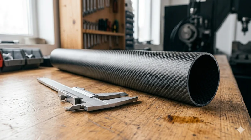
Most production tubes are roll-wrapped around a mandrel from 2x2 twill or unidirectional carbon prepreg with an epoxy matrix, then cured in an autoclave or under vacuum. The layup favours stiffness and hoop strength over maximum fibre volume, because the part must resist collapsing under vacuum and clamp load without cracking at the coupler. A typical wall is 1.0 to 2.0 mm in two or three plies, and a resin-rich inner surface is avoided because it can shed particles into the airflow.
Thermal limits matter more here than on a cosmetic panel. A standard toughened epoxy is comfortable to about 120 °C continuous, while a high-temperature matrix such as bismaleimide holds 180 °C or more. That difference decides whether a tube can sit near a turbocharger or exhaust runner or must be shielded, and even a good tube picks up radiant heat from nearby hot parts.
| Parameter | Street / naturally aspirated | Turbocharged | Motorsport |
|---|---|---|---|
| Internal diameter (mm) | 65-80 | 76-102 | 80-102 |
| Wall thickness (mm) | 1.0-1.5 | 1.5-2.0 | 1.5-2.5 |
| Continuous temperature limit (°C) | 100-120 | 120-150 | 150-180 |
| Pressure / vacuum rating (bar) | 2-4 | 4-7 | 6-10 |
| Indicative mass (kg) | 0.4-0.6 | 0.6-0.8 | 0.7-0.9 |
| Indicative price (USD, single unit) | 120-260 | 180-380 | 320-700 |
Prices are indicative and move with tooling amortisation, port count and finish. A one-off prototype with printed flanges costs far more per unit than a run of two hundred.
Bore, length and tuning effects
Cross-sectional area sets the velocity for a given mass flow. A 60 mm bore on an engine that needs more air creates a pressure drop the throttle body cannot recover, while an oversized 102 mm bore on a small engine slows the incoming charge and dulls throttle response. As a working rule, keep gas velocity in the tube between 60 and 90 m/s at peak flow for a street car, and match the tube bore to the throttle body inlet rather than exceeding it by more than about 10 percent.
Length matters because the duct is part of a resonant system. Changing tube length shifts the rpm at which the intake resonates favourably, so a longer tube can help low-rpm torque while a shorter one favours top-end flow. That is why a well-engineered kit is tested on a flow bench or chassis dyno across the rev range rather than at one peak point. Typical gains depend on the full intake path, and any honest supplier will say so.
Airflow data is the useful common language for comparison. A tube assembly measured on a flow bench at a fixed depression can be compared directly against the stock part at the same condition:
| Bore (mm) | Bench flow at 28 in H2O (CFM, indicative) | Typical application |
|---|---|---|
| 60 | 280-330 | 1.0-1.6 L, stock replacement |
| 70 | 400-470 | 1.6-2.0 L naturally aspirated |
| 76 | 480-560 | 2.0-2.5 L, mild turbo |
| 89 | 640-740 | Turbocharged, high flow |
| 102 | 820-960 | Motorsport, large turbo |
The CFM column is indicative bench data for a short straight tube with smooth ends; real installed flow is always lower because of bends, couplers and the filter. Use it to rank options, not to predict a dyno result.
Carbon fiber tube connection details that decide reliability
Nearly every field failure of an intake tube happens at a joint. Carbon fiber tube connection design therefore deserves as much attention as the layup. Three methods dominate.
- Silicone coupler over a bead: the tube end is machined or moulded with a rolled bead, and a 4-ply silicone sleeve plus a stainless T-bolt clamp holds it. This is the most forgiving method and the easiest to service.
- Bonded aluminium spigot: an anodised insert is bonded into the tube bore with a toughened epoxy, giving a hard surface for the clamp and a metal interface for a MAF housing.
- Machined flange with O-ring: used where the tube bolts directly to the throttle body or airbox, with a captured seal and a defined bolt pattern.
Whatever the method, three details control success: a bead or lip at least 3 mm high so the coupler cannot slide off under boost, a bond line of 0.1-0.3 mm on a properly abraded and degreased surface, and clamp torque set by the manufacturer rather than by feel. A clamp tightened until the silicone bulges will cut the coupler and leak under load.
Where a carbon fiber tube chassis application appears
Outside the induction system, the same tube stock appears as a carbon fiber tube chassis element: crash structures, side-impact bars, drive-shaft tunnels, seat mounts and cooling ducts on low-volume and motorsport vehicles. Requirements differ sharply from an intake duct. A chassis tube is specified for bending and torsional stiffness, crush behaviour and bonded joint strength, usually at a larger diameter and thicker wall. Suppliers who serve both applications quote diameter, wall, straightness, resin system and test evidence separately, because a tube that performs perfectly as an intake duct may be unsuitable as a structural member.
Fitment, mounting and heat management
Engine movement is the most common cause of cracked tubes and popped couplers. A tube bolted rigidly at both ends to an engine that moves several millimetres under load will fatigue. Hard-mount one end, use a flexible coupler plus a compliant bobbin mount at the other, and keep 5-10 mm of clearance to any hot or moving part. Route vacuum, PCV and sensor ports with at least 3 mm of wall around them and add an extra ply where a port carries hose load.
Mass airflow sensor placement matters just as much. The sensor needs a straight run of at least ten bore diameters upstream and five downstream to read a stable signal, and it must keep the same clock position as the stock housing. Moving a MAF closer to a bend introduces turbulence that shows up as fuel trim errors and a check-engine light, which customers usually blame on the tube.
Inspection, testing and batch control
Incoming inspection is short but specific. Check bore with a gauge or pin at both ends and in the middle; a tube that tapers by more than 0.5 mm will not seal consistently at the couplers. Check wall thickness at four clock positions at each end for ovality and thin spots. Tap test any bonded spigot and look for voids along the bond line. Pressure test the assembly at 1.5 times the working rating and hold for 60 seconds. Finally, confirm the internal surface is smooth and free of loose fibres, because anything that can detach will reach the engine.
For repeatability, fix the mandrel, prepreg lot, cure cycle and bead dimensions, and record bore, wall and mass for every unit. A 20 gram difference between two tubes of the same part number usually points to a layup or resin-content deviation that will also show up as a stiffness difference.
Frequently Asked Questions
Does a carbon fiber intake tube add power on its own?
Not by itself. It can reduce pressure loss and heat pickup relative to a restrictive or hot stock duct, but typical gains depend on the full intake path, including filter, throttle body, manifold and calibration. Treat it as one component in a system and test the whole system.
What wall thickness should I specify?
1.0-1.5 mm suits a naturally aspirated street application, 1.5-2.0 mm is typical for turbocharged cars where the tube sees boost and more vibration, and 1.5-2.5 mm is used in motorsport with added heat shielding.
Will a carbon tube survive next to a turbocharger?
Only with the right resin system and shielding. Standard toughened epoxy handles roughly 120 °C continuous; near a turbo you want a high-temperature matrix rated to 180 °C or more, plus a reflective heat shield or wrap.
Can I bond a carbon tube to an aluminium MAF housing?
Yes, with a toughened two-part epoxy, a properly abraded and degreased surface, a controlled 0.1-0.3 mm bond line and a design that puts the joint in shear rather than peel. A mechanical bead or pin should back up the bond.
Conclusion
Specify a carbon fiber intake tube the way you would specify any other structural duct: bore matched to the throttle body and airflow target, wall matched to boost and vibration, resin system matched to the temperature it will actually see, and joints designed so the coupler cannot slip. Then verify with a flow bench comparison and a pressure test rather than a peak power claim. YongXian produces roll-wrapped and filament-wound intake tubes, bonded spigots, machined flanges and matching carbon tube stock for chassis use, quoted against your drawings, port layout and temperature requirement. Send your bore, wall, port schedule and operating temperature through contact our team and we will reply with an indicative price and a prototype plan.
Related Articles
- Carbon Fiber Arrow Shafts: Spine Selection and Performance
- Car Carbon Fiber Gear Knob: Shift Knob Buying Guide
- Carbon Fiber Road Glide Fairing: Lightweight Upgrade Options
- Carbon Fiber Road Glide Fender: Aftermarket Options
- Carbon Fiber Bike Parts: Frame and Component Upgrade Guide
- Carbon Fiber Sheets for Cars: Interior, Exterior and Structural Uses
Interested in Our Products?
Contact our team for competitive pricing and technical specifications.
Get a QuoteRelated Products

Carbon Fiber Plate — 3K Twill T700 1.5mm
Thin 1.5mm carbon fiber plate with 3K twill weave surface. Lightweight and stiff, commonly used for covers, panels, drone bodies, and applications requiring a premium aesthetic appearance.

Carbon Fiber Plate — 3K Twill T700 3.0mm
Medium-thickness 3.0mm carbon fiber plate offering significantly higher load capacity while maintaining attractive 3K twill finish. Suitable for structural brackets, reinforcement plates, and load-bearing panels.

Square Carbon Fiber Tube — 3K Twill T700
Square cross-section carbon fiber tube manufactured with 3K twill weave for torsional strength. Preferred for structural frames, trusses, and support columns where rectangular geometry offers design flexibility.

Round Carbon Fiber Tube — UD Unidirectional T700
Unidirectional (UD) round tube with all fibers aligned axially for maximum longitudinal stiffness. Ideal for applications requiring high bending rigidity with minimal weight, such as shafts, struts, and structural reinforcements.
Round Carbon Fiber Tube — 3K Plain Weave T700
Standard round carbon fiber tube manufactured from Toray T700 grade fiber with 3K plain weave. Offers balanced strength and stiffness for general industrial applications including robotics, automation, sports equipment, and aerospace structures.