
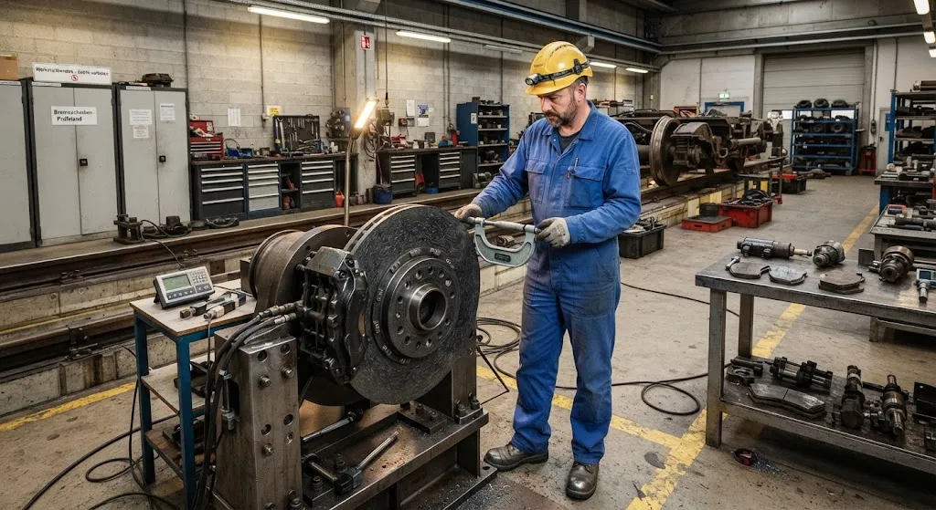
High-speed rail systems operating at 350 km/h and above face extreme braking demands that push conventional cast iron and steel brake discs to their material limits. A single emergency braking event from 350 km/h generates kinetic energy of approximately 50 MJ per trainset — equivalent to the energy
Introduction
High-speed rail systems operating at 350 km/h and above face extreme braking demands that push conventional cast iron and steel brake discs to their material limits. A single emergency braking event from 350 km/h generates kinetic energy of approximately 50 MJ per trainset — equivalent to the energy content of 1.2 liters of gasoline — all of which must be absorbed by the brake disc-rotor system and dissipated as heat. At these energy levels, cast iron discs experience thermal cracking, surface oxidation, and dimensional instability that limit service life to 80,000-120,000 km between replacements, while steel discs suffer from thermal fatigue and warping.
Carbon fiber reinforced ceramic composite (C/SiC) brake discs — manufactured by infiltrating a carbon fiber preform with silicon carbide through chemical vapor infiltration (CVI) or polymer infiltration and pyrolysis (PIP) — offer a fundamentally different thermal response. The carbon fiber reinforcement provides damage tolerance and thermal conductivity, while the SiC matrix provides high-temperature strength and wear resistance. This article evaluates C/SiC brake disc performance for high-speed rail, examining the material systems, thermal management challenges, wear behavior, and cost-benefit calculations that determine whether composite discs make economic sense for rail operators.
Material Systems for Railway Brake Discs
C/SiC composite brake discs for railway applications use a carbon fiber architecture optimized for thermal shock resistance and friction stability. The material system design balances competing requirements: high thermal conductivity to distribute heat quickly, high specific heat capacity to absorb energy, and a friction coefficient that remains stable across the wide temperature range encountered during braking:
| Property | C/SiC Composite | Cast Iron (GJW)** | Steel (30CrMoV)** | Significance for Braking |
|---|---|---|---|---|
| Density | 2.0-2.2 g/cm³ | 7.2 g/cm³ | 7.8 g/cm³ | 65-72% weight reduction |
| Max operating temperature | 1,200°C | 600°C | 650°C | Higher thermal capacity |
| Thermal conductivity (RT) | 25-40 W/(m·K) | 48 W/(m·K) | 42 W/(m·K) | Comparable heat distribution |
| Specific heat capacity | 800-1,000 J/(kg·K) | 460 J/(kg·K) | 480 J/(kg·K) | More energy absorbed per kg |
| Friction coefficient (dry) | 0.30-0.45 | 0.35-0.40 | 0.30-0.38 | Stable across temperature range |
| Thermal shock resistance | Excellent | Moderate | Moderate | Resists cracking under rapid heating |
**GJW = graphite jet gray cast iron; 30CrMoV = chromium-molybdenum-vanadium alloy steel
The key advantage of C/SiC over cast iron is not thermal conductivity — which is actually lower — but the combination of high maximum operating temperature and high specific heat capacity. A C/SiC disc can absorb 2-3 times more thermal energy per kilogram before reaching critical temperature, and it maintains structural integrity at temperatures where cast iron softens and oxidizes. The friction coefficient stability is also critical: cast iron discs exhibit significant friction fade above 500°C as the surface oxide layer changes character, while C/SiC maintains consistent friction from ambient to 800°C.
Thermal Management During Braking
The thermal challenge in high-speed rail braking is not average energy absorption — it is peak temperature management during emergency stops. The thermal timeline of a single emergency brake application reveals the severity of the challenge:
- 0-3 seconds: Brake pads contact disc surface, converting kinetic energy to heat at rates of 10-15 MW per disc. Surface temperature rises from ambient to 400-600°C almost instantaneously.
- 3-8 seconds: Heat conducts into disc body, creating steep thermal gradients of 200-400°C between surface and core. Cast iron discs develop surface microcracks during this phase.
- 8-25 seconds: Train decelerates from 200 km/h to stop. Total energy absorption reaches 25-35 MJ per disc. Peak surface temperature on cast iron discs can reach 700-800°C.
- 25-120 seconds: Cool-down phase. Disc cools through radiation and convection, with cooling rates of 50-100°C/min for cast iron and 30-60°C/min for C/SiC (lower thermal conductivity slows cooling but reduces thermal stress).
C/SiC composites manage this thermal shock through two mechanisms. First, the carbon fiber reinforcement has a very low coefficient of thermal expansion (CTE) of 1-3 × 10⁻⁶/°C, compared with 10-12 × 10⁻⁶/°C for cast iron, meaning the disc expands less and generates lower thermal stresses during rapid heating. Second, the fiber reinforcement provides crack-arrest capability: when surface cracks initiate in the SiC matrix under thermal stress, the carbon fiber bridges the crack and prevents propagation, maintaining structural integrity even with surface damage.
Wear Behavior and Service Life
Brake disc wear in high-speed rail is driven by two mechanisms: abrasive wear from friction material contact and oxidative wear at high temperatures. C/SiC composites address both mechanisms differently than cast iron:
- Abrasive wear: The SiC matrix provides surface hardness of 15-25 GPa, significantly harder than cast iron (2-3 GPa). This reduces the wear rate from friction material contact by 40-60%, extending disc service life proportionally.
- Oxidative wear: At temperatures above 600°C, cast iron surfaces oxidize rapidly, forming a brittle oxide layer that spalls under mechanical loading. C/SiC composites form a thin, adherent SiO₂ layer at high temperatures that actually protects the surface rather than degrading it.
- Thermal fatigue: The repeated heating-cooling cycles of service create thermal fatigue cracks in cast iron. C/SiC's fiber reinforcement provides fatigue crack growth resistance that extends fatigue life by 3-5× compared to cast iron.
Service life data from operational high-speed rail systems confirms the advantage: C/SiC brake discs have demonstrated 300,000-500,000 km service life in European and Asian high-speed rail operations, compared with 80,000-120,000 km for cast iron discs. This 3-5× life extension is the primary economic driver for composite adoption, as it reduces disc replacement frequency, associated downtime, and lifecycle material costs.
Manufacturing Process and Quality Control
Producing C/SiC brake discs for railway applications requires a multi-step manufacturing process with tight quality control:
- Carbon fiber preform fabrication: Carbon fiber cloth is woven or needled into a disc-shaped preform with controlled fiber architecture. The preform density and fiber orientation determine the final thermal and mechanical properties.
- Chemical vapor infiltration (CVI): The preform is placed in a high-temperature furnace and exposed to silicon-containing gas mixtures (typically methyltrichlorosilane in hydrogen) at 900-1,100°C. SiC deposits on the fiber surfaces over 100-300 hours, gradually densifying the preform to 65-80% theoretical density.
- Polymer infiltration and pyrolysis (PIP): An alternative or complementary process where a silicon-containing polymer is infiltrated into the preform, then pyrolyzed at 1,000-1,200°C to convert to SiC. Multiple PIP cycles are needed to achieve target density.
- Machining and balancing: The final disc is machined to dimensional tolerances of ±0.05 mm on the friction surface and balanced to within 5 g·cm to prevent vibration at high rotational speeds.
Quality control includes ultrasonic inspection for delamination, X-ray CT scanning for internal porosity, friction coefficient testing on dynamometers, and thermal cycling validation. Railway certification standards (EN 15380, UIC 540) require prototype testing including 1,000+ simulated emergency stops and 500,000 km durability testing before production approval.
Cost-Benefit Analysis for Rail Operators
The economic case for C/SiC brake discs in high-speed rail involves trading higher initial material cost against lower lifecycle cost:
| Cost Factor | Cast Iron Disc | C/SiC Disc | Net Effect |
|---|---|---|---|
| Initial cost per disc | $800-1,200 | $4,000-6,000 | C/SiC 4-5× higher |
| Service life (km) | 80,000-120,000 | 300,000-500,000 | C/SiC 3-5× longer |
| Replacements per 1M km | 8-12 | 2-3 | C/SiC 70-75% fewer |
| Weight per disc | 45-65 kg | 12-18 kg | C/SiC 65-72% lighter |
| Energy savings (lighter weight) | Baseline | 3-5% traction energy reduction | Significant at fleet scale |
| Maintenance downtime | Higher (frequent replacement) | Lower (extended intervals) | Higher train availability |
For a fleet of 20 high-speed trainsets operating at 1.5 million km per year, the lifecycle cost calculation typically shows C/SiC discs achieving cost parity within 3-5 years and providing 25-40% total cost savings over a 15-year fleet life. The weight reduction benefit — saving approximately 30-50 kg per axle — also reduces track wear and traction energy consumption, benefits that accrue to the infrastructure operator and energy supplier rather than the train operator directly.
Frequently Asked Questions
Why not use carbon-carbon (C/C) brake discs instead of C/SiC?
Carbon-carbon composites offer excellent high-temperature performance but suffer from catastrophic oxidation above 450°C in atmospheric conditions without protective coatings. C/SiC's SiC matrix provides inherent oxidation resistance that eliminates the need for environmental barrier coatings, making it more practical for railway applications where discs are exposed to rain, snow, and atmospheric conditions during operation. C/C discs remain preferred for aerospace applications (aircraft brakes) where the operating environment is more controlled, but C/SiC's robustness makes it the better choice for railway service where maintenance conditions are less controlled.
How does rain affect C/SiC brake disc performance?
Rain on the brake disc surface reduces the friction coefficient by 15-25% during the initial braking phase as water creates a thin lubricating film between pad and disc. However, the high thermal conductivity of C/SiC and the disc's rotational energy quickly evaporate the water film — typically within 2-5 seconds of brake application — restoring full friction. Cast iron discs take longer to dry due to lower surface temperature capability, and the water can accelerate oxidative wear. C/SiC discs actually benefit from occasional rain exposure, as it cleans the disc surface and removes friction material deposits that can cause hot spots.
What happens if a C/SiC disc cracks during service?
C/SiC composites are designed for damage tolerance: the carbon fiber reinforcement bridges cracks in the SiC matrix and prevents catastrophic failure. Small surface cracks (up to 5-10 mm) are acceptable in service and do not affect braking performance, as the friction surface continues to function normally. Inspection intervals are set at 50,000-100,000 km to monitor crack growth, and discs are replaced when cracks exceed depth limits specified in railway maintenance standards. The fail-safe design means that even with visible cracking, the disc maintains sufficient structural integrity for continued service at reduced speed until the next maintenance opportunity.
Conclusion
Carbon fiber reinforced ceramic composite brake discs represent a proven technology for high-speed rail applications where the combination of 65-72% weight reduction, 3-5× service life extension, and superior thermal stability under emergency braking conditions provides clear lifecycle cost advantages over cast iron. The C/SiC material system's ability to maintain stable friction from ambient to 800°C and resist thermal shock cracking makes it particularly suited for the demanding duty cycles of high-speed rail service. While initial material costs remain 4-5× higher than cast iron, the lifecycle economics favor composite adoption for any fleet operating above 200 km/h with annual mileage exceeding 500,000 km per trainset.
For high-speed rail procurement managers evaluating brake disc options, C/SiC composites offer a technology pathway that reduces maintenance burden, extends service intervals, and lowers total cost of ownership — benefits that compound across large fleets over long service lives. Explore our carbon fiber composite products for railway applications, or contact our engineering team for material specifications and qualification support for your rolling stock programs.
Part of topic
Related Articles
- Carbon Fiber Composite Rebar for Corrosive Environments: Marine and Chemical Plant Applications
- Carbon Fiber Helicopter Rotor Blade Spar Design: Fatigue Life and Erosion Protection
- Carbon Fiber Automotive Side Panels: High-Gloss Class-A Surface Finish for Premium Vehicles
- Carbon Fiber Deployable Structures for Satellites: Boom and Antenna Mast Applications
- Carbon Fiber Electromagnetic Interference Shielding: EMI Solutions for Electronics and 5G
- Carbon Fiber Drone Propeller Blades: Lightweight Design for Endurance and Payload
Interested in Our Products?
Contact our team for competitive pricing and technical specifications.
Get a QuoteRelated Products

Carbon Fiber Plate — 3K Twill T700 1.5mm
Thin 1.5mm carbon fiber plate with 3K twill weave surface. Lightweight and stiff, commonly used for covers, panels, drone bodies, and applications requiring a premium aesthetic appearance.

Carbon Fiber Plate — 3K Twill T700 3.0mm
Medium-thickness 3.0mm carbon fiber plate offering significantly higher load capacity while maintaining attractive 3K twill finish. Suitable for structural brackets, reinforcement plates, and load-bearing panels.

Square Carbon Fiber Tube — 3K Twill T700
Square cross-section carbon fiber tube manufactured with 3K twill weave for torsional strength. Preferred for structural frames, trusses, and support columns where rectangular geometry offers design flexibility.

Carbon Fiber Plate — UD Unidirectional T700
Unidirectional carbon fiber plate with all fibers oriented in a single direction for maximum strength along the fiber axis. Essential for structural reinforcements, splints, and applications where load direction is predictable.

Round Carbon Fiber Tube — UD Unidirectional T700
Unidirectional (UD) round tube with all fibers aligned axially for maximum longitudinal stiffness. Ideal for applications requiring high bending rigidity with minimal weight, such as shafts, struts, and structural reinforcements.