
Introduction The helicopter rotor blade spar is one of the most demanding structural applications of carbon fiber composite technology. Each blade must simultaneously carry centrifugal loads of 50,000-150,000 Newtons, bending moments from aerodynamic lift and drag, torsional loads from pitch changes
Introduction
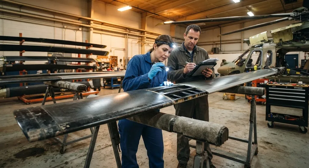
The helicopter rotor blade spar is one of the most demanding structural applications of carbon fiber composite technology. Each blade must simultaneously carry centrifugal loads of 50,000-150,000 Newtons, bending moments from aerodynamic lift and drag, torsional loads from pitch changes, and impact damage from rain, sand, hail, and foreign object debris — all while rotating at tip speeds of 200-250 meters per second for 20,000-40,000 flight hours without structural failure. The spar, the primary beam running spanwise through the blade, carries the dominant centrifugal and bending loads and therefore determines the blade's fatigue life, maintenance interval, and ultimate safety.
Carbon fiber reinforced polymer spars have replaced aluminum and titanium in virtually all modern helicopter rotor blades because carbon fiber offers a fatigue endurance limit that metals cannot match: properly designed CFRP spars can sustain billions of load cycles without crack initiation, compared to aluminum spars that develop detectable fatigue cracks after 5,000-10,000 flight hours. This article explains the design principles, material choices, and erosion protection strategies that enable carbon fiber spars to meet the extreme demands of rotorcraft service, providing practical guidance for blade manufacturers and operators evaluating spar material and design options.
Helicopter Rotor Blade Spar Architecture and Load Path
The rotor blade spar is typically a closed-cell box beam or D-spar configuration running from the blade root attachment to the tip, with a cross-section that tapers in both chord and thickness toward the tip. The spar must carry three simultaneous load cases:
- Centrifugal tension: As the blade rotates, centrifugal force creates axial tension along the spar. For a typical 5-meter blade rotating at 400 RPM, the centrifugal load at the root is approximately 80,000-120,000 Newtons. This load is primarily carried by unidirectional carbon fiber plies oriented along the spar axis (0-degree plies), which provide the high tensile strength needed to resist centrifugal pull-out.
- Flapwise bending: Aerodynamic lift creates a bending moment that varies along the span, maximum at the root and zero at the tip. The spar resists this bending through its section modulus, which is maximized by placing high-modulus carbon fiber plies in the spar caps (top and bottom surfaces) where bending stresses are highest. Spar cap thickness typically varies from 8-12 mm at the root to 2-4 mm at the tip.
- Chordwise bending and torsion: Drag loads and pitch changes create chordwise bending and torsional loads that are resisted by the spar web (the vertical shear panel connecting the upper and lower caps) and the trailing edge structure. The spar web typically uses plus or minus 45-degree carbon fiber plies optimized for shear resistance.
The interaction between these load cases creates a complex multiaxial stress state that requires careful ply orientation design. Modern blade spars use a hybrid layup combining unidirectional, biaxial, and triaxial carbon fiber fabrics to optimize the spar for each load case while maintaining interlaminar strength and damage tolerance.
Material Selection for Helicopter Rotor Blade Spar Design
The material system for a carbon fiber rotor blade spar must satisfy three competing requirements: high fatigue life under cyclic loading, damage tolerance to impact events, and environmental resistance to moisture, temperature, and ultraviolet radiation. The key material parameters and their effects on spar performance are:
| Material Parameter | Typical Specification | Effect on Spar Performance | Trade-off |
|---|---|---|---|
| Fiber type | Intermediate modulus (T800/T900 class) | Higher fatigue strength than standard modulus | Higher cost, lower strain to failure |
| Fiber areal weight | 150-300 g/m2 | Heavier fabrics reduce layup time but increase resin content | Weight penalty vs manufacturing efficiency |
| Resin system | Toughened epoxy, Tg above 120 degrees C | Damage tolerance and hot-wet performance | Higher processing temperature, longer cure |
| Fiber volume fraction | 55-62% | Higher Vf increases strength and stiffness | Lower Vf improves impact resistance |
| Interleaf material | Thermoplastic veil or rubber particle film | Improves interlaminar fracture toughness | Adds weight and processing complexity |
The choice between standard modulus and intermediate modulus carbon fiber is the most consequential decision in spar design. Standard modulus fiber (T700 class, 230 GPa) provides excellent fatigue life at lower cost, but intermediate modulus fiber (T800 class, 294 GPa) allows thinner spar caps with the same stiffness, reducing blade weight by 5-10%. For military rotorcraft where every kilogram of weight savings translates directly into payload or range, intermediate modulus fiber is standard. For civil helicopters operating under weight and cost constraints, standard modulus fiber with optimized layup design often provides the best balance of performance and economics.
The resin system must be toughened to survive the impact events that occur during service — rain erosion at high droplet impact velocities, sand and gravel ingestion, and hard landings that impose transient loads far exceeding design limits. Toughened epoxy systems with rubber or thermoplastic particle modification provide Mode I interlaminar fracture toughness (G1c) values of 500-1000 J/m2, compared to 150-250 J/m2 for unmodified epoxies. This improvement in damage tolerance directly translates to longer service life between blade replacements.
Leading-Edge Erosion Protection Systems
While the spar carries the primary structural loads, the blade's leading edge is the most vulnerable surface to erosion damage. Rain erosion at helicopter tip speeds of 200-250 meters per second creates droplet impact pressures exceeding 100 MPa, sufficient to remove unprotected composite surfaces within hours of flight. Three erosion protection approaches are used in production rotorcraft:
- Metal erosion shields: Stainless steel or titanium strips bonded or mechanically fastened to the leading edge. Metal shields provide the highest erosion resistance and are easily replaced when worn, but add 5-15% to blade weight and introduce galvanic corrosion risks at the carbon fiber-metal interface. The interface must be insulated with a fiberglass or adhesive layer to prevent galvanic degradation.
- Polyurethane erosion tapes:Filled polyurethane or polyurea elastomer tapes applied to the leading edge surface. These tapes absorb rain droplet impact energy through elastic deformation, providing good erosion protection at minimal weight penalty (0.1-0.3 kg per square meter). Tape replacement intervals of 500-1000 flight hours are typical, and the replacement can be performed in the field without blade removal.
- Thermoplastic leading edge caps: Injection-molded or compression-molded thermoplastic (polyurethane, polyamide, or PEEK) caps bonded to the leading edge. These caps combine structural stiffness with erosion resistance and can be designed as integral parts of the blade structure. The material must be compatible with the carbon fiber spar adhesive and withstand the same thermal cycling and UV exposure as the blade structure.
The selection among these approaches depends on the operating environment, maintenance philosophy, and cost constraints. Military rotorcraft operating in desert environments typically use metal shields due to sand erosion severity, while civil helicopters in temperate climates often use polyurethane tapes for their ease of replacement and low weight.
Fatigue Life Assessment and Testing
Qualifying a carbon fiber rotor blade spar for service requires demonstrating fatigue life that meets or exceeds the design target through a combination of analysis and physical testing. The standard approach includes:
- S-N curve characterization: Coupon-level fatigue testing of the spar material system under constant-amplitude cyclic loading to establish the S-N relationship (stress vs number of cycles to failure). Carbon fiber composites typically exhibit fatigue endurance limits at 55-65% of static ultimate strength, compared to 30-40% for aluminum alloys. The S-N data is used to predict spar life under the variable-amplitude loading encountered in service.
- Component-level testing: Full-scale or sub-scale spar sections subjected to combined centrifugal, bending, and torsion loading in a test rig that simulates the multiaxial stress state of actual flight. Component tests validate the spar design under realistic loading conditions and reveal failure modes that coupon tests cannot capture, such as interlaminar delamination propagation under combined loading.
- Full-scale blade testing: Complete rotor blades tested on a Whirl Tower or equivalent rotating test facility to demonstrate fatigue life under actual rotational loading. Full-scale tests are the final qualification step and typically require 10-20 million load cycles (representing 20,000-40,000 flight hours) without structural failure.
- Damage tolerance demonstration: Tests showing that the spar can sustain specified damage scenarios (impact dents, manufacturing defects, bolt holes) without catastrophic failure, meeting the damage tolerance requirements of certification standards such as CS-27 (Europe) or FAR Part 27 (United States).
The fatigue life target for a production spar is typically 40,000 flight hours with a safety factor of 4 on loads, meaning the spar must demonstrate survival under loads four times the maximum expected operational loads for the design life. Achieving this target requires tight process control during manufacturing, with fiber volume fraction controlled within plus or minus 2%, void content below 2%, and no foreign object inclusions above the detectability threshold of the quality assurance inspection.
Frequently Asked Questions
How does carbon fiber spar fatigue life compare to aluminum spars?
Carbon fiber spars offer significantly longer fatigue life than aluminum spars. Under typical rotorcraft loading, aluminum alloy spars develop detectable fatigue cracks after 5,000-10,000 flight hours, requiring regular inspection intervals and eventual replacement. Carbon fiber spars, when properly designed and manufactured, can sustain 20,000-40,000 flight hours without crack initiation. The key difference is that carbon fiber composites do not have a true fatigue limit in the same sense as metals — they exhibit progressive stiffness degradation rather than discrete crack growth. This progressive degradation is easier to monitor through periodic blade track and balance checks, and it provides warning before structural failure rather than sudden catastrophic fracture.
What is the main cause of carbon fiber spar failure in service?
The most common cause of spar failure in service is not fatigue loading but rather damage from external sources: rain and sand erosion thinning the leading edge until the spar cap is exposed, impact damage from foreign objects creating delaminations that propagate under cyclic loading, and lightning strike damage that ablates fiber and resin. Manufacturing defects — such as porosity, fiber misalignment, or resin-rich areas — can also initiate failure if they exceed the quality acceptance criteria. Regular inspection programs that combine visual examination, eddy current testing, and blade track analysis are essential for detecting these damage sources before they compromise structural integrity.
How are carbon fiber spars repaired when damage is detected?
Repair procedures depend on the type and extent of damage. For minor surface erosion or small impact dents that do not compromise the spar cap thickness, bonded repair patches using carbon fiber prepreg and vacuum bag curing are standard practice. For more significant damage — delaminations extending over a significant area, or fiber breakage in the spar cap — the repair may require removal of the damaged section and replacement with a bonded or bolted splice. Repairs are performed according to manufacturer-approved repair manuals and must be documented and inspected before the blade is returned to service. The repair capability of carbon fiber spars is one advantage over metallic spars, which are more limited in their repair options due to fatigue sensitivity of repair joints.
Conclusion
Carbon fiber rotor blade spars represent the current state of the art in helicopter structural design, offering fatigue life, damage tolerance, and weight advantages that aluminum and titanium cannot match. The spar's design integrates material selection, layup architecture, and erosion protection into a system that must survive 20,000-40,000 flight hours under the most demanding cyclic loading in aerospace. For blade manufacturers, the path to qualification runs through rigorous coupon, component, and full-scale testing against certification standards, combined with manufacturing process control that ensures consistent quality across production batches.
For operators evaluating spar material and design options, the critical factors are demonstrated fatigue life data, repair capability, and the total cost of ownership over the blade service interval. Explore our carbon fiber products for aerospace structural applications, or contact our engineering team to discuss spar material selection and fatigue life analysis for your rotorcraft program.
Part of topic
Related Articles
- Carbon Fiber High-Speed Train Brake Discs: Thermal Stability and Wear Resistance
- Carbon Fiber Composite Rebar for Corrosive Environments: Marine and Chemical Plant Applications
- Carbon Fiber Automotive Side Panels: High-Gloss Class-A Surface Finish for Premium Vehicles
- Carbon Fiber Deployable Structures for Satellites: Boom and Antenna Mast Applications
- Carbon Fiber Electromagnetic Interference Shielding: EMI Solutions for Electronics and 5G
- Carbon Fiber Drone Propeller Blades: Lightweight Design for Endurance and Payload
Interested in Our Products?
Contact our team for competitive pricing and technical specifications.
Get a QuoteRelated Products

Carbon Fiber Plate — 3K Twill T700 1.5mm
Thin 1.5mm carbon fiber plate with 3K twill weave surface. Lightweight and stiff, commonly used for covers, panels, drone bodies, and applications requiring a premium aesthetic appearance.

Carbon Fiber Plate — 3K Twill T700 3.0mm
Medium-thickness 3.0mm carbon fiber plate offering significantly higher load capacity while maintaining attractive 3K twill finish. Suitable for structural brackets, reinforcement plates, and load-bearing panels.

Square Carbon Fiber Tube — 3K Twill T700
Square cross-section carbon fiber tube manufactured with 3K twill weave for torsional strength. Preferred for structural frames, trusses, and support columns where rectangular geometry offers design flexibility.

Carbon Fiber Plate — UD Unidirectional T700
Unidirectional carbon fiber plate with all fibers oriented in a single direction for maximum strength along the fiber axis. Essential for structural reinforcements, splints, and applications where load direction is predictable.

Round Carbon Fiber Tube — UD Unidirectional T700
Unidirectional (UD) round tube with all fibers aligned axially for maximum longitudinal stiffness. Ideal for applications requiring high bending rigidity with minimal weight, such as shafts, struts, and structural reinforcements.