
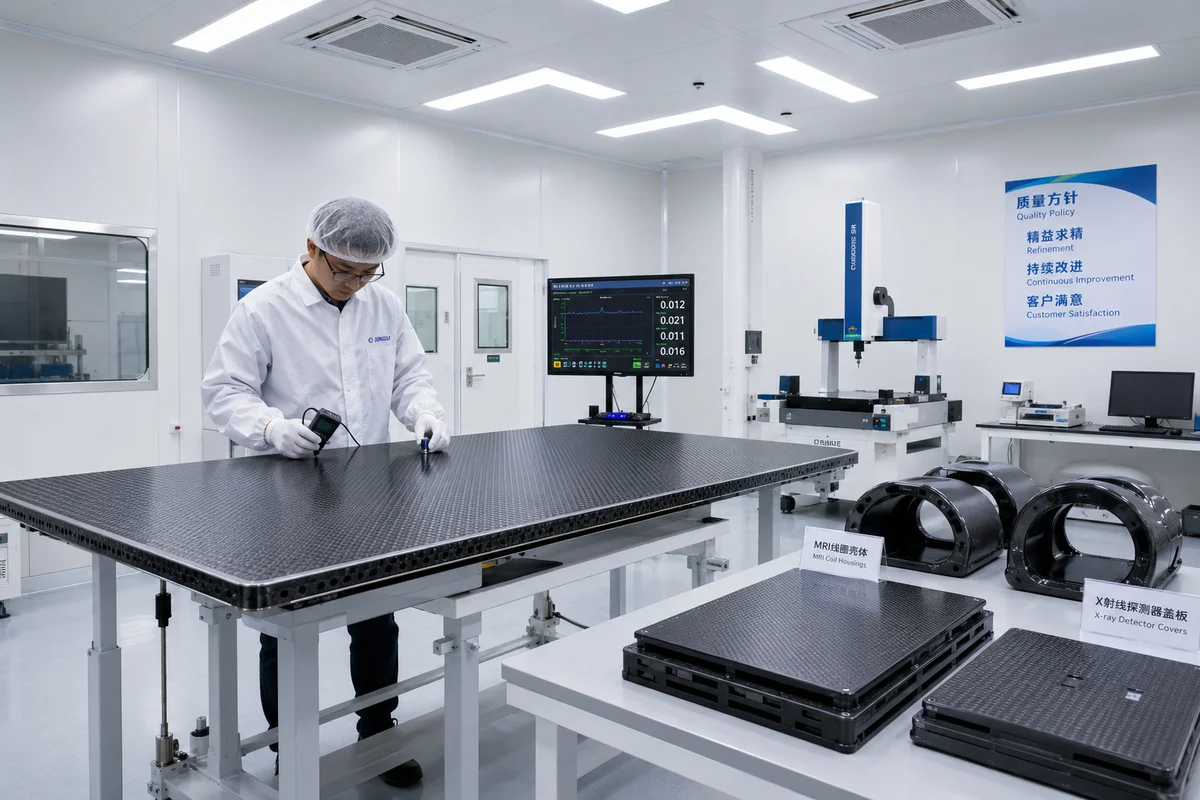
Carbon fiber components in medical imaging equipment — CT patient tables, X-ray cassette panels, MRI coil housings, and radiolucent surgical tools. Material requirements, manufacturing processes, and market data for B2B medical device suppliers.
Carbon Fiber's Unique Role in Medical Imaging
Carbon fibre composites are essential in medical imaging equipment because of a unique combination of properties: radiolucency (transparency to X-rays and gamma rays), high stiffness-to-weight ratio, dimensional stability, and electrical neutrality (no ferromagnetic response). In 2025, the medical imaging component market consumed approximately 2,200 tonnes of carbon fibre globally, growing at 8–10 % annually as CT and MRI installation rates increase in ageing populations and emerging markets.
Key Applications and Material Requirements
| Application | Component | Key Requirement | Material Form | Typical Fibre Grade |
|---|---|---|---|---|
| CT scanner | Patient table top | Low X-ray attenuation; stiffness for up to 300 kg patient load; 1.5 m × 0.5 m panel | Carbon fibre sandwich panel (CFRP skin + foam core) | T700 (12K–24K); intermediate modulus for thinner panels |
| CT scanner | Gantry covers | Radiolucent; lightweight for tilt mechanism; EMI shielding | Woven CFRP (200–400 gsm) with conductive coating | T700 woven (3K–12K) |
| X-ray / DR | Cassette panel / detector housing | Uniform radiolucency across panel; dimensional stability < 0.1 mm over temperature range | Unidirectional CFRP laminate 0.5–1.0 mm thick | T700 or T800 UD prepreg |
| MRI | RF coil housing | Non-ferromagnetic; no eddy current; dimensional stability in 1.5–7 T field | Thin woven CFRP (0.3–0.8 mm) with epoxy or PEEK matrix | T700 3K woven (PEEK matrix for 7 T MRI) |
| MRI | Patient table / bridge | MRI-compatible (non-magnetic); high stiffness; weight limit < 30 kg | Pultruded CF profiles + sandwich panels | T700 (50K for pultrusion) |
| Surgical | Radiolucent retractors / forceps | X-ray transparent during fluoroscopy; sterilizable (autoclave 134 °C); 5+ year life | Unidirectional CFRP laminate or injection-moulded CF/PEEK | T700 or IM7 with PEEK matrix |
| Radiotherapy | Treatment couch top | Low beam attenuation; precise indexing; Ion chamber cut-out compatibility | CFRP honeycomb sandwich panel | T700 (12K–24K) |
CT Patient Table: The Most Demanding Application
The CT patient table top is arguably the most technically demanding carbon fibre component in medical imaging. It must be thin enough for minimal X-ray attenuation (typically 12–18 mm total thickness including core) yet stiff enough to support patients up to 300 kg without measurable deflection (limit: 5 mm under 200 kg centre load per IEC 60601-2-44). The panel typically uses a carbon fibre-epoxy skin (0.5–1.0 mm per face) sandwiching a rigid foam or honeycomb core (10–16 mm thick). At YongXian, we manufacture CT table top panels (YX-CT series) using 12K T700 woven fabric with a cyanate ester resin system for low moisture absorption, achieving an X-ray attenuation equivalent of 0.3–0.5 mm aluminium at 120 kVp.
X-Ray Detector Panels: Uniformity Is Everything
For digital X-ray detector panels, the carbon fibre cover must have uniform radiolucency across the entire imaging area (typically 35 cm × 43 cm). Any local variation in fibre volume fraction or thickness creates image artefacts. We achieve this through precise prepreg layup with thickness tolerance ± 0.05 mm across the panel, using a single ply of UD prepreg oriented at 0°/90° to balance stiffness and radiolucency uniformity. The panel must also withstand repeated handling and cleaning with hospital-grade disinfectants (500+ cycles of isopropyl alcohol and quaternary ammonium compounds).
MRI Coil Housings: Non-Ferromagnetic and Eddy Current-Free
MRI components face the strictest material constraints. Any ferromagnetic material is prohibited within the 5-gauss line. Carbon fibre itself is inherently non-magnetic, but the choice of fibre type, sizing, and resin system matters. For high-field MRI (3 T and 7 T), we specify PEEK matrix instead of epoxy to eliminate any trace of polar compounds that could cause dielectric heating. The laminate thickness is kept to 0.3–0.8 mm to minimize eddy current induction during gradient coil switching. Our YX-MRI series prepreg uses PEEK with a low-resin-content formulation (32–36 %) and a non-woven carrier to ensure consistent conductivity across the part.
Market Data and Growth Projections
- Global CT scanner market: 48,000 units installed (2025), growing to 55,000 by 2028. Each CT requires 1 patient table + gantry covers = approximately 8–12 kg of carbon fibre.
- Global MRI market: 22,000 units installed (2025), growing to 27,000 by 2028. Each MRI uses 5–8 kg of carbon fibre (coil housing + table).
- Digital X-ray detector market: 210,000 panels produced in 2025, each requiring 0.2–0.4 kg of carbon fibre. Growth driven by replacement of analogue systems in developing markets.
- Carbon fibre consumption in medical imaging: 2,200 tonnes (2025) → projected 3,500 tonnes by 2030 (CAGR 8–10 %).
- Key OEM regions: USA (35 %), Germany (18 %), Japan (12 %), China (22 %), rest of world (13 %).
Q: What is the X-ray attenuation of carbon fibre compared to aluminium?
A: Carbon fibre has approximately 20–30 % of the X-ray attenuation of aluminium at typical diagnostic energies (60–120 kVp). A 1 mm thick carbon fibre laminate is equivalent to 0.2–0.3 mm aluminium in attenuation. This is why carbon fibre is universally preferred for X-ray and CT components — it allows the same image quality at lower radiation dose, or higher image quality at the same dose.
Q: Can carbon fibre be used inside the MRI bore (near the imaging volume)?
A: Yes, but only with careful material selection. Inside the MRI bore, carbon fibre components must be non-conductive in loop configurations (to avoid induced currents) and magnetically neutral. We recommend: (1) fibre with high electrical resistivity (standard modulus fibre is acceptable; avoid high-modulus pitch-based fibre which is more conductive); (2) PEEK or cyanate ester resin matrix (not standard epoxy, which may contain polar additives); (3) non-conductive sizing; and (4) geometric design that avoids closed conductive loops. For direct patient-contact components inside the bore, we also add a medical-grade silicone coating for patient comfort and cleanability.
Q: What certifications are required for carbon fibre medical imaging components?
A: At minimum: ISO 13485 (medical device quality management), ISO 10993-5 (cytotoxicity), ISO 10993-10 (skin sensitization), and in-vitro biocompatibility per USP Class VI for patient-contact components. For CT tables specifically, IEC 60601-2-44 (particular requirements for CT scanners) requires static load testing to 300 kg, dynamic fatigue testing (10,000 cycles at 150 kg), and X-ray attenuation measurement. At YongXian, we provide full biocompatibility test reports and design history files to support our customers' FDA 510(k) or CE MDR submissions.
Part of topic
Related Articles
- Carbon Fiber Mooring for Floating Offshore Wind: Fatigue and Corrosion in Deep Water
- Carbon Fiber Bicycle Frame Optimization: Layup Design and Manufacturing for Competitive Racing
- Carbon Fiber CFRP Retrofit for Infrastructure: Bridge and Building Seismic Strengthening
- Carbon Fiber Medical Imaging Equipment: Lightweight Gantry and Couch Structures for MRI/CT
- Carbon Fiber EV Battery Enclosures: Crash Safety and Electromagnetic Shielding Design
- Carbon Fiber Structures for Low-Altitude Economy: UAV Airframes and eVTOL Components
Interested in Our Products?
Contact our team for competitive pricing and technical specifications.
Get a QuoteRelated Products

Carbon fiber standard plate-3k stripe
Lightweight, ultra-rigid standard sheets for drone fuselages, robot housings, facades and structural applications.

Carbon Fiber Plate — 3K Twill T700 1.5mm
Thin 1.5mm carbon fiber plate with 3K twill weave surface. Lightweight and stiff, commonly used for covers, panels, drone bodies, and applications requiring a premium aesthetic appearance.

Square Carbon Fiber Tube — 3K Twill T700
Square cross-section carbon fiber tube manufactured with 3K twill weave for torsional strength. Preferred for structural frames, trusses, and support columns where rectangular geometry offers design flexibility.

Carbon Fiber Plate — 3K Twill T700 3.0mm
Medium-thickness 3.0mm carbon fiber plate offering significantly higher load capacity while maintaining attractive 3K twill finish. Suitable for structural brackets, reinforcement plates, and load-bearing panels.

Carbon Fiber Plate — UD Unidirectional T700
Unidirectional carbon fiber plate with all fibers oriented in a single direction for maximum strength along the fiber axis. Essential for structural reinforcements, splints, and applications where load direction is predictable.