
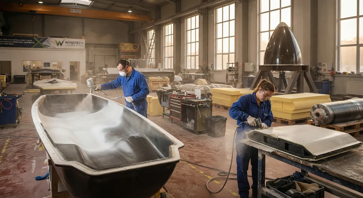
When wind turbine designers talk about composite materials, the conversation usually centers on rotor blades. Yet every turbine also carries a second family of composite structures: the nacelle cover that encloses the gearbox, generator, and yaw system, and the spinner that caps the rot
Introduction
When wind turbine designers talk about composite materials, the conversation usually centers on rotor blades. Yet every turbine also carries a second family of composite structures: the nacelle cover that encloses the gearbox, generator, and yaw system, and the spinner that caps the rotor hub and blends the blade roots into the airflow. On a modern multi-megawatt turbine these are substantial components — a nacelle cover for a 5-8 MW machine spans 12-18 meters in length and weighs several tonnes even in glass fiber — and they sit at the top of a tower that is already bending under rotor thrust. Every kilogram of nacelle mass pulls on the tower, the foundation, and the overall cost of the turbine, which is why carbon fiber is steadily moving into these components.
This article examines how nacelle covers and spinners are designed aero-structurally, how carbon fiber reduces mass and dynamic loads at the tower top, and how their design contributes to noise reduction — the environmental constraint that now drives much of modern wind turbine engineering.
The Functions of Nacelle Covers and Spinners
A nacelle cover performs four jobs simultaneously. It is the weather enclosure that protects the drive train from rain, snow, and salt; it is an aerodynamic shell that must minimize drag and avoid flow separation over the tower top; it carries the service platforms, lighting, and access hatches that technicians rely on; and increasingly, it is an acoustic element in the turbine's noise budget. The spinner adds a fifth function: it smooths the airflow transition from the rotating hub to the blade roots, reducing the aerodynamic noise and efficiency loss caused by the open root gap on older designs. Because both components are large, thin-walled, and stiffness-driven, they are natural candidates for sandwich construction — and for carbon fiber where stiffness per kilogram matters most.
Material Selection: Carbon versus Glass
Nacelle covers and spinners have traditionally been built from glass fiber-reinforced polyester or epoxy, and glass remains the value option. Carbon fiber enters where its higher modulus and lower density create a decisive mass or deflection advantage. The comparison below reflects typical values for a 6-8 MW turbine's nacelle cover skins and major stiffening structures:
| Property | E-glass/epoxy | Carbon/epoxy | Hybrid carbon/glass |
|---|---|---|---|
| Fiber modulus (GPa) | 72-85 | 230-294 | 120-180 (blended) |
| Laminate density (g/cm³) | 1.9-2.0 | 1.5-1.6 | 1.6-1.7 |
| Relative skin stiffness at equal mass | 1x | 2.5-3.5x | 1.8-2.5x |
| Typical cover mass, 6-8 MW (tonnes) | 4.0-5.5 | 2.5-3.5 | 2.8-4.0 |
| Relative material cost per kg | 1x | 6-10x | 2-4x |
| Typical use in nacelle | Outer skins, panels | Main load-carrying frames, local stiffening | Large covers balancing cost and stiffness |
Full-carbon covers are rare because the cost is hard to justify on a component that is mostly stiffness-driven rather than strength-critical. The dominant pattern in recent designs is selective hybridization: carbon unidirectional or fabric plies in the main structural frames, the bedplate-mounted brackets, and the largest unsupported spans, with glass in the large cosmetic panels and the interior. This captures most of the mass and deflection benefit at a fraction of the all-carbon cost.
Aero-Structural Design for Load Reduction
The structural argument for lighter covers and spinners is a chain reaction that affects the whole turbine. Mass at the tower top increases the tower's bending moment, the foundation's overturning moment, and the loads transmitted through the yaw bearing and main frame. Removing mass at the top therefore reduces not just the component's own cost but the cost of the tower, foundation, and drivetrain supports. The structural load paths in a nacelle cover are simple to describe but exacting to design:
- Main structural frames: longitudinal and transverse girders carry the dead weight of the cover, the service loads, and the aerodynamic pressure of the design wind; these are the natural home for carbon reinforcement.
- Sandwich panels: the large unsupported surfaces between frames are glass or hybrid skins on foam or balsa core, sized for deflection limits and resistance to panel flutter under wind.
- Spinner structure: a conical sandwich shell with a carbon-reinforced hub ring where it bolts to the rotating hub, sized for centrifugal, wind, and fatigue loads over a 20-25 year life.
- Access and inspection: hatches, walkways, and tie-down points add local loads that must be carried without visible deflection of the outer surface.
Because covers and spinners are stiffness- and deflection-driven, carbon's 2.5-3.5x stiffness advantage at equal mass translates directly into either a lighter panel for the same deflection or a stiffer panel at the same weight. For a 6-8 MW turbine, carbon hybridized into the main frames and largest spans typically removes 1-1.5 tonnes from the tower top, which cascades into measurable savings in tower steel and foundation concrete.
Noise Reduction Design
Noise is now a dominant constraint in onshore wind siting, and covers and spinners contribute to the acoustic budget in two ways. First, the spinner's aerodynamic shaping directly reduces trailing-edge and root-gap noise at the blade root, where much of mid-frequency aerodynamic noise originates. Second, the cover and spinner surfaces themselves must not add tonal or broadband noise: laminar flow must be maintained over the shell, surface joints must be flush and faired, and the panels must not resonate or transmit drive-train noise outward. The design measures are:
- Aerodynamic shaping: a smooth, low-curvature spinner profile and faired cover transitions prevent flow separation and the associated low-frequency noise and buffeting.
- Damping: sandwich cores and constrained-layer damping treatments raise the panel's loss factor, suppressing vibration and structure-borne noise radiating from the gearbox and generator.
- Acoustic sealing: gasketed joints, acoustic seals around hatches, and internal absorption in the cover cavity reduce the transmission of mechanical noise to the outside.
These measures typically shave 1-3 dB from the total turbine sound power level — modest on paper but often decisive for meeting night-time setback limits that permit the turbine to operate at full tip speed.
Manufacturing and Surface Requirements
Nacelle covers and spinners are manufactured almost exclusively by open or closed molding of sandwich construction. The production pattern is consistent across the industry: gel coat applied to the mold for a durable, UV-stable, low-drag outer surface; glass or hybrid skins infused with resin (vacuum infusion is the standard for larger panels); foam or balsa core; and bonded-in metal inserts and frames for attachments. Carbon, where used, is placed as unidirectional or fabric plies in the frames and hub ring, either co-infused with the glass or pre-cured and co-bonded. Surface quality is a first-order requirement — a nacelle cover is one of the largest visible surfaces on a wind farm, and poor surface finish both looks wrong and adds aerodynamic drag and noise. Fire-retardant resin systems are specified for the interior surfaces adjacent to electrical equipment, and lightning protection is integrated through the spinner into the hub structure.
Frequently Asked Questions
Why not build nacelle covers entirely from carbon fiber?
Nacelle covers are stiffness-driven rather than strength-critical, so carbon's main benefit is lower mass at equal stiffness. Full-carbon construction is technically feasible and would save another 20-30% of mass versus hybrid designs, but carbon costs 6-10x more per kilogram than glass, and on a component where deflection limits rather than stress limits drive the design, the extra stiffness buys little. The industry-standard answer is selective hybridization: carbon in the main structural frames, the bedplate brackets, and the largest unsupported spans, glass in the cosmetic panels. This captures most of the mass and deflection benefit at a fraction of the all-carbon cost.
How much weight does carbon fiber save on a modern turbine's nacelle?
On a 6-8 MW turbine, hybridizing carbon into the main frames and largest spans typically removes 1-1.5 tonnes from the nacelle cover and spinner combination versus a full-glass design — roughly 20-30% of the cover mass. The savings compound: less mass at the tower top reduces the tower bending moment and foundation overturning moment, which allows a lighter tower section and smaller foundation. Over the turbine's 25-year life, the system-level savings in tower steel, concrete, and logistics are typically worth several times the added material cost of the carbon itself.
How do nacelle covers and spinners contribute to wind turbine noise?
Two mechanisms matter. The spinner's aerodynamic shaping reduces trailing-edge and root-gap noise at the blade root, where much mid-frequency aerodynamic noise originates; a smooth low-curvature profile prevents flow separation that would add low-frequency buffeting noise. The cover must then avoid radiating mechanical noise: sandwich cores and constrained-layer damping suppress panel vibration from the gearbox and generator, gasketed joints and acoustic seals block sound paths, and internal absorption treats the cover cavity. Together these typically shave 1-3 dB from the total sound power level — often decisive for meeting night-time noise limits that otherwise force reduced tip speed.
Conclusion
Nacelle covers and spinners demonstrate how carbon fiber's value proposition works for large, stiffness-driven components that are not strength-critical. Selective hybridization — carbon in the main frames, bedplate brackets, and largest unsupported spans, glass elsewhere — removes 1-1.5 tonnes from the tower top of a 6-8 MW turbine, cascading into lighter towers, smaller foundations, and better logistics, while the aerodynamic and acoustic design of these shells contributes directly to the noise reductions that new wind projects need for siting approval.
For turbine OEMs and component suppliers, the practical factors are carbon-glass hybrid laminate design, sandwich core selection, and surface quality at production scale. Explore our carbon fiber fabric and prepreg range for structural frames and large-span panels, or contact our engineering team to discuss hybrid laminate design and prototyping for your next nacelle program.
Part of topic
Related Articles
- Carbon Fiber Tube for Sale: Comparing Listings and Avoiding Bad Specs
- Carbon Fiber Engine Parts: High-Temperature Performance for Racing and Performance Vehicles
- Carbon Fiber Body Parts: Automotive Exterior Panels and Structural Components
- Carbon Fiber Drone Body Manufacturing: Monocoque Design and Production Methods
- Carbon Fiber Drone Parts Supplier: FPV Frames, Arms and Structural Components
- Filament Wound Epoxy Tubes: Industrial Applications from Oil and Gas to Aerospace
Interested in Our Products?
Contact our team for competitive pricing and technical specifications.
Get a QuoteRelated Products

Carbon fiber standard plate-3k stripe
Lightweight, ultra-rigid standard sheets for drone fuselages, robot housings, facades and structural applications.

Carbon Fiber Plate — 3K Twill T700 3.0mm
Medium-thickness 3.0mm carbon fiber plate offering significantly higher load capacity while maintaining attractive 3K twill finish. Suitable for structural brackets, reinforcement plates, and load-bearing panels.

Carbon Fiber Plate — 3K Twill T700 1.5mm
Thin 1.5mm carbon fiber plate with 3K twill weave surface. Lightweight and stiff, commonly used for covers, panels, drone bodies, and applications requiring a premium aesthetic appearance.

Square Carbon Fiber Tube — 3K Twill T700
Square cross-section carbon fiber tube manufactured with 3K twill weave for torsional strength. Preferred for structural frames, trusses, and support columns where rectangular geometry offers design flexibility.

Carbon Fiber Plate — UD Unidirectional T700
Unidirectional carbon fiber plate with all fibers oriented in a single direction for maximum strength along the fiber axis. Essential for structural reinforcements, splints, and applications where load direction is predictable.