
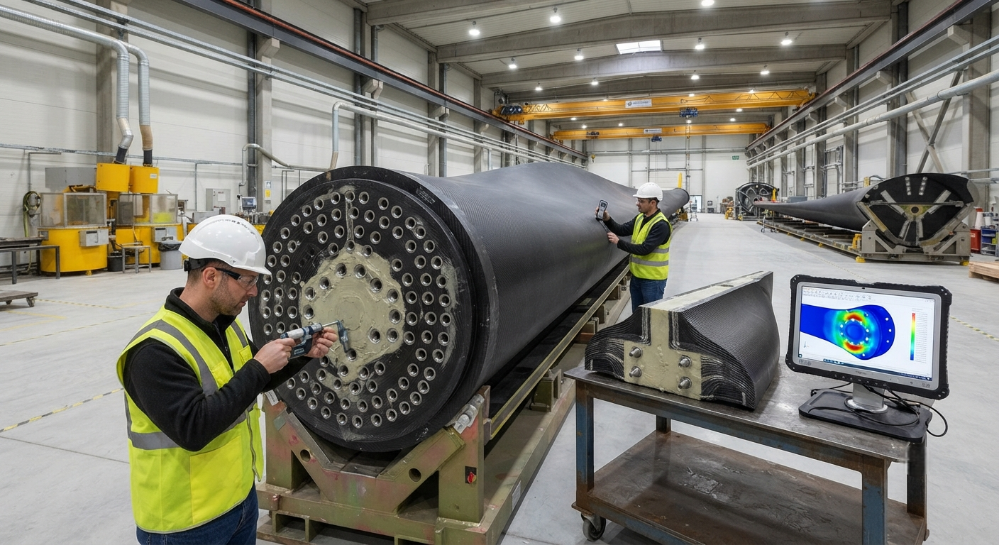
The blade root connection transfers aerodynamic bending moments exceeding 30,000 kN·m from the composite blade shell to the pitch bearing and hub. This article provides a comparative technical analysis of T-bolt, threaded stud, and embedded insert connection designs for megawatt-class carbon fiber wind turbine blades, with emphasis on galvanic corrosion prevention, fatigue performance, and design considerations for offshore environments.
The blade root connection is arguably the most structurally critical interface in a wind turbine. It transfers the entire aerodynamic bending moment — which can exceed 30,000 kN·m for an 8 MW turbine — from the composite blade shell into the metallic pitch bearing and hub. A failure at this interface is catastrophic, typically resulting in blade separation and complete turbine loss. With modern offshore wind turbines reaching 15+ MW and blade lengths exceeding 115 meters, the mechanical demands on root connection designs have intensified dramatically.
Three primary connection architectures dominate the industry: T-bolt connections (also called barrel nut or stud bushing connections), threaded stud connections, and embedded metal insert connections. Each approach presents distinct advantages in load transfer characteristics, manufacturing complexity, inspectability, and field serviceability. This article provides a comparative technical analysis of these designs for megawatt-class carbon fiber wind turbine blades, with particular emphasis on the interface between carbon fiber composite structures and metallic fastening systems — a perennial engineering challenge due to galvanic corrosion risk, stiffness mismatch, and thermal expansion coefficient differences.
Comparative Analysis of Root Connection Designs
The selection of a blade root connection architecture depends on blade size, manufacturing process, fatigue loading spectrum, and maintenance philosophy. The following table summarizes the key attributes of each design approach as implemented in current production blades ranging from 40 to 115 meters.
| Parameter | T-Bolt Connection | Threaded Stud Connection | Embedded Insert Connection |
|---|---|---|---|
| Typical blade length range | 40–85 m | 60–115+ m | 50–100 m |
| Number of fasteners (8 MW class) | 70–90 T-bolts | 80–120 studs | 60–100 inserts |
| Bolt diameter range | M24–M36 | M30–M48 | M24–M42 |
| Preload per fastener | 250–400 kN | 350–600 kN | 300–500 kN |
| Fatigue class (ISO 4016) | 10.9 / 12.9 | 10.9 with rolled thread | 10.9 / 12.9 |
| Galvanic isolation method | Polymer sleeve + washer | Titanium stud or coated steel | Glass fiber isolation layer |
| Field replaceability | Accessible from outside | Requires internal access | Difficult — potted in epoxy |
| Manufacturing complexity | Moderate — drilling + potting | High — precise thread alignment | Moderate — casting in layup |
| Inspectability (in-service) | Borescope through bolt hole | Visual + torque check | Ultrasonic through insert |
| Relative cost per connection | 1.0 (baseline) | 1.3–1.6× | 1.1–1.4× |
T-Bolt Connection Design Details
The T-bolt connection remains the most widely adopted root connection design in blades up to 85 meters. In this configuration, a threaded barrel nut (T-nut or stud bushing) is potted into the blade root laminate during blade manufacturing, oriented perpendicular to the blade axis. A bolt passes through the pitch bearing flange, through a clearance hole in the blade root laminate, and threads into the barrel nut. The T-bolt name derives from the cross-sectional shape of the barrel nut, which resembles a "T" or an inverted "L" in profile.
Key design considerations for T-bolt connections in carbon fiber blades include:
- Potting compound selection: The barrel nut is typically potted into the root laminate using a high-strength epoxy or vinyl ester filled paste with a compressive strength exceeding 120 MPa and a glass transition temperature above 80°C. The potting compound transfers the bolt preload into the composite laminate through shear — requiring careful control of the potting annulus geometry (typically 2-5 mm gap around the barrel nut).
- Load introduction length: The minimum embedment length of the barrel nut in the root laminate must be calculated to ensure the load transfer stress in the potting compound does not exceed allowable limits. For a 10.9 grade M30 bolt with 360 kN preload, a minimum embedment length of 120-150 mm is typical, with the hole diameter 8-12 mm larger than the barrel nut outer diameter.
- Galvanic corrosion prevention: Carbon fiber's cathodic potential (-0.3 V vs. SCE) combined with steel bolts creates a galvanic couple that accelerates corrosion of the steel component in the presence of moisture. Prevention measures include: isolating the barrel nut with a glass fiber sleeve at least 1 mm thick, applying a polymer washer between the bolt head and blade surface, sealing the annulus with a non-conductive sealant, and specifying stainless steel or titanium barrel nuts for offshore blades.
- Load distribution: The T-bolt connection creates a non-uniform load distribution along the blade root circumference, with bolts at the leading and trailing edges experiencing the highest cyclic loads. Finite element analysis must be performed to optimize pitch bearing bolt holes and adjust preload values per bolt position.
Threaded Stud and Embedded Insert Designs
For blades exceeding 85 meters — particularly offshore blades above 10 MW — threaded stud connections have become increasingly common. In this design, a high-strength steel or titanium stud is threaded directly into a tapped metal insert that is laminated directly into the blade root during the infusion process. The stud extends through the pitch bearing flange and is secured with a nut on the bearing side. This configuration eliminates the need for an external bolt head protruding from the blade surface, providing a cleaner aerodynamic profile and reducing lightning strike attachment risk.
Embedded insert connections represent a third approach where a flanged metal cylinder with internal threads is incorporated into the blade root laminate layup before infusion. The flange features multiple holes through which the carbon fiber or glass fiber reinforcement passes during layup, mechanically interlocking the insert with the composite structure. This design provides the most direct load path but complicates manufacturing — the inserts must be precisely positioned before infusion and secured against movement during the vacuum and resin flow process.
Fatigue Performance and Certification
Blade root connections are subject to the most demanding fatigue loading of any wind turbine component, typically experiencing 10⁷ to 10⁸ load cycles over a 20-25 year design life. The fatigue spectrum includes gravity-induced edgewise bending (once per revolution, 10⁷-10⁸ cycles), turbulent wind-induced flapwise bending (10⁵-10⁷ cycles with varying amplitude), and extreme loads from 50-year gust events (O(10) cycles). Certification to IEC 61400-23 (full-scale structural testing) requires the blade root connection to survive: static proof load at 1.3× design load without permanent deformation, fatigue test covering 2× design life (typically 2×10⁶ equivalent cycles at increased amplitude), and a residual strength test after fatigue loading demonstrating at least 1.0× ultimate design load capacity.
FAQ
How does galvanic corrosion between carbon fiber and steel bolts affect blade root connection design?
Galvanic corrosion is a critical design concern when carbon fiber composite (cathodic, -0.3 V vs. SCE) contacts steel fasteners (anodic, -0.6 to -0.7 V vs. SCE). In the presence of an electrolyte — seawater for offshore turbines, or condensed moisture for onshore turbines — the galvanic current accelerates steel corrosion by 3-10× compared to isolated exposure. This can lead to premature bolt failure, loss of preload, and ultimately root connection failure. Design countermeasures include: mandatory galvanic isolation using glass fiber or polymer sleeves at every carbon-metal interface, blind hole designs that prevent electrolyte ingress to the barrel nut cavity, corrosion-resistant fastener materials (stainless steel 316L, titanium grade 5, or Inconel 718 for extreme offshore environments), and periodic borescope inspection of barrel nut cavities for corrosion evidence. Onshore turbines typically specify hot-dip galvanized or Dacromet-coated steel bolts with polymer sleeve isolation, while offshore turbines increasingly mandate titanium bolts despite 4-6× higher material cost.
What is the typical preload loss (relaxation) in blade root T-bolt connections during the first year of turbine operation?
Blade root T-bolt connections experience preload relaxation from several sources: creep in the potting compound (typically 3-5% of initial preload), creep in the composite laminate under sustained compression bearing stress (2-4%), settling and embedment of threaded interfaces (1-2%), and thermal cycling effects during operation (1-3% per 100°C temperature swing between hub interior and blade surface). Total relaxation in the first year ranges from 8-15% of initial preload, with the majority occurring in the first 3-6 months. After the initial bedding-in period, annual relaxation drops to 1-3%. Turbine manufacturers typically specify initial preload at 70-80% of bolt yield strength, with retorque scheduling after 500-1000 hours of operation, then annually for the first 3 years, and every 3-5 years thereafter. Ultrasonic bolt tension measurement provides the most accurate preload verification (±3% accuracy), compared to torque-only methods (±15-25% accuracy).
How do root connection designs differ between onshore and offshore wind turbine blades?
Offshore blade root connections face additional challenges that drive design differences: saltwater exposure requires titanium or high-grade stainless steel fasteners with enhanced galvanic isolation and sealed cavities; higher fatigue loading from continuous wave and turbulence exposure requires thicker root laminates, larger bolt diameters (typically one size larger than equivalent onshore), and higher preload safety margins (1.5× vs. 1.25× for onshore); limited service access window reduces maintenance frequency, driving adoption of designs with longer maintenance intervals (5 years vs. 2-3 years for onshore); lightning strike density is higher offshore, requiring enhanced grounding paths through the root connection (typically 800 kA-rated down-conductor systems compared to 400 kA for onshore); and corrosion protection coatings must meet ISO 12944 C5-M (offshore) classification versus C3-C4 for onshore. These factors typically add 15-25% to the cost of the root connection system for offshore blades compared to comparable onshore designs.
Conclusion
The blade root connection remains one of the most engineering-intensive aspects of megawatt-class wind turbine blade design. Whether selecting T-bolt, threaded stud, or embedded insert configurations, designers must balance load transfer efficiency, manufacturing complexity, corrosion protection, inspectability, and lifecycle cost. For carbon fiber blades in particular, galvanic isolation and load introduction into the orthotropic composite structure require specialized design attention that differs significantly from conventional glass fiber blade root connections. As blade lengths push beyond 115 meters for 15+ MW offshore turbines, root connection technology continues to evolve toward larger-diameter studs, more sophisticated isolation systems, and enhanced fatigue life prediction methods. Yongxian Carbon Fiber supplies precision-machined carbon fiber blade root sub-assemblies and performs T-bolt insertion and potting services for blade manufacturers worldwide. Our engineering team offers design review support and root connection FEA services. Contact our wind energy division to discuss your blade root connection requirements.
Part of topic
Related Articles
- Carbon Fiber Mooring for Floating Offshore Wind: Fatigue and Corrosion in Deep Water
- Carbon Fiber Bicycle Frame Optimization: Layup Design and Manufacturing for Competitive Racing
- Carbon Fiber CFRP Retrofit for Infrastructure: Bridge and Building Seismic Strengthening
- Carbon Fiber Medical Imaging Equipment: Lightweight Gantry and Couch Structures for MRI/CT
- Carbon Fiber EV Battery Enclosures: Crash Safety and Electromagnetic Shielding Design
- Carbon Fiber Structures for Low-Altitude Economy: UAV Airframes and eVTOL Components
Interested in Our Products?
Contact our team for competitive pricing and technical specifications.
Get a QuoteRelated Products

Carbon fiber standard plate-3k stripe
Lightweight, ultra-rigid standard sheets for drone fuselages, robot housings, facades and structural applications.

Square Carbon Fiber Tube — 3K Twill T700
Square cross-section carbon fiber tube manufactured with 3K twill weave for torsional strength. Preferred for structural frames, trusses, and support columns where rectangular geometry offers design flexibility.

Carbon Fiber Plate — 3K Twill T700 3.0mm
Medium-thickness 3.0mm carbon fiber plate offering significantly higher load capacity while maintaining attractive 3K twill finish. Suitable for structural brackets, reinforcement plates, and load-bearing panels.

Carbon Fiber Plate — 3K Twill T700 1.5mm
Thin 1.5mm carbon fiber plate with 3K twill weave surface. Lightweight and stiff, commonly used for covers, panels, drone bodies, and applications requiring a premium aesthetic appearance.

Carbon Fiber Plate — UD Unidirectional T700
Unidirectional carbon fiber plate with all fibers oriented in a single direction for maximum strength along the fiber axis. Essential for structural reinforcements, splints, and applications where load direction is predictable.