
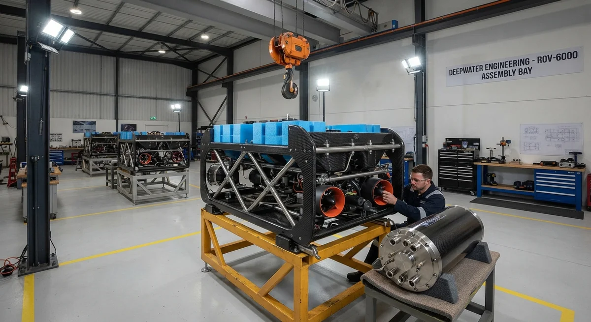
Technical analysis of carbon fiber composites for underwater vehicle frames and pressure housings, with material property comparisons, design optimization strategies, and a deep-sea ROV case study.
# Carbon Fiber for ROVs and AUVs: Lightweight Frames and Pressure-Resistant Housings
The global fleet of remotely operated vehicles (ROVs) and autonomous underwater vehicles (AUVs) has expanded rapidly in the 2020s, driven by offshore oil and gas infrastructure inspection, deep-sea mineral exploration, submarine cable maintenance, and defense applications. As operational depth ratings increase beyond 3,000 meters and mission durations extend to weeks or months, the structural design of the vehicle frame and pressure housings has become a critical differentiator in vehicle performance. Carbon fiber composites have emerged as the material of choice for both load-bearing frames and pressure-resistant enclosures, offering specific strength and stiffness metrics that significantly outperform traditional metallic alloys in the underwater environment.
Frame Structures: Stiffness-to-Weight Optimization
The frame (or chassis) of an ROV/AUV serves as the structural backbone to which thrusters, manipulator arms, sensors, payload modules, and buoyancy elements are attached. Frame design is governed primarily by bending stiffness requirements—the frame must resist torsional loads of up to 850 N·m during high-speed transit maneuvers (3–5 knots) and withstand static payloads of 150–600 kg at the manipulator arm base without exceeding a tip deflection of 5 mm at the arm flange.
Table 3: Material Comparison for ROV/AUV Frame Structures at 3,000 m Depth Rating
| Property | 6061-T6 Aluminum | Ti-6Al-4V Titanium | 316L Stainless Steel | CFRP (T700SC, Quasi-Isotropic) | CFRP (M40J, High Modulus) |
| Density (g/cm³) | 2.70 | 4.43 | 7.95 | 1.55 | 1.60 |
| Tensile modulus (GPa) | 68.9 | 113.8 | 193 | 55 (quasi-isotropic) | 95 (quasi-isotropic) |
| Specific stiffness (GPa/(g/cm³)) | 25.5 | 25.7 | 24.3 | 35.5 | 59.4 |
| Tensile strength (MPa) | 310 | 950 | 485 | 620 | 580 |
| Corrosion resistance in seawater | Moderate (requires anodizing) | Excellent | Good (susceptible to crevice corrosion) | Excellent (no galvanic with careful isolation) | Excellent |
| Frame mass for 1.2 m × 0.8 m × 0.6 m space frame (kg) | 18.5 | 32.2 | 55.0 | 10.8 | 8.5 |
| Manufacturer cost index (aluminum = 1.0) | 1.0 | 6.8 | 1.8 | 4.2 | 7.5 |
| Fatigue endurance at 10⁷ cycles, seawater (MPa) | 95 | 350 | 180 | 320 | 250 |
The specific stiffness advantage of CFRP—35.5 GPa/(g/cm³) for standard modulus fiber in a quasi-isotropic layup, rising to 59.4 GPa/(g/cm³) for high-modulus fiber—translates directly into vehicle payload capacity. A CFRP frame weighing 10.8 kg provides equivalent stiffness to an 18.5 kg aluminum frame (42% weight saving) or a 55 kg stainless steel frame (80% weight saving). In a typical 300 kg AUV, every kilogram saved on the frame can be reallocated to battery capacity (≈180 Wh/kg with modern Li-ion packs), extending mission endurance by approximately 8–12 minutes per kilogram of frame weight reduction.
Pressure-Resistant Housings
The pressure housing (also called the pressure vessel or dry enclosure) houses mission-critical electronics including the navigation computer, inertial measurement unit (IMU), acoustic modem, power distribution board, and battery pack. For a housing designed to operate at 3,000 m depth (30 MPa external pressure), the wall thickness required to prevent buckling is the dominant design constraint.
Metallic pressure housings for deep-rated vehicles are typically machined from 6061-T6 aluminum (wall thickness 8–14 mm for a 250 mm diameter housing) or Ti-6Al-4V titanium (wall thickness 5–9 mm), with titanium offering a superior depth rating per unit wall thickness. CFRP pressure housings present a more complex design problem because the material is anisotropic and the failure mode—buckling-driven delamination under hydrostatic compression—differs fundamentally from metallic yielding.
Critical parameters for CFRP pressure housings:
- Layup optimization for hydrostatic compression: A CFRP pressure housing optimized for 30 MPa external pressure typically uses a [±45/0₂/±45/90]s layup sequence, with the hoop-directed 0° plies providing 65% of the circumferential strength and the ±45° plies handling shear transfer from end closures. A 250 mm internal diameter housing with 6.2 mm wall thickness achieves a safety factor of 1.8 against buckling at 30 MPa, compared to 11.0 mm required for 6061-T6 aluminum (safety factor 1.5) and 7.0 mm for Ti-6Al-4V (safety factor 2.0).
- Water absorption and dimensional stability: Immersion in seawater at 30 MPa and 2°C (typical deep-ocean conditions) causes epoxy matrix water absorption of 1.2–1.8% by weight over 30 days, leading to a reduction in Tg of 18–25°C and a 0.08–0.12% increase in housing dimensions. This hygroscopic swelling must be accounted for in O-ring gland design; a CFRP housing designed for 3,000 m operation requires O-ring groove depth 0.15–0.20 mm greater than an equivalent aluminum housing to accommodate expansion without seal extrusion.
- Penetrator integration: Feedthroughs for electrical and optical connectors are bonded into the CFRP housing wall using a two-step process: a tapered hole is machined with a 5° included angle diamond bur, pre-treated with a silane coupling agent, and the titanium or stainless steel connector sleeve is bonded using a toughened epoxy (e.g., 3M Scotch-Weld DP420, lap shear strength 28 MPa). Pull-out testing at 2× design pressure (60 MPa) is mandatory for certification.
- Fiber selection: Standard modulus fibers (Toray T700SC, 230 GPa tensile modulus) are preferred for large pressure housing diameters (>300 mm), where buckling stability—driven by laminate bending stiffness—is the critical failure mode. High-modulus fibers (M40J, 377 GPa) offer no advantage in this regime because the ±45° plies that dominate shear performance benefit only marginally from higher fiber modulus.
Case Study: DeepWater Engineering ROV-6000
DeepWater Engineering's ROV-6000 work-class vehicle, rated to 6,000 m depth and launched in early 2026, represents the current state of the art in CFRP-intensive ROV construction. The vehicle carries 24 kg more battery capacity (42 kWh vs 30 kWh) than its titanium-framed predecessor by weight saved on the mainframe, enabling 32-hour continuous missions at 4-knot cruising speed—a 28% increase over the baseline. The CFRP main electronics housing (320 mm ID × 780 mm length, 8.5 mm wall thickness) has accumulated 1,200 hours of operational time across 14 dives to depths exceeding 4,500 m with zero housing failures. Post-dive inspection using industrial CT scanning has confirmed no progressive delamination after 60 pressure cycles to 60 MPa (test pressure for 6,000 m rating).
Key Considerations for CFRP in Underwater Vehicle Structures:
- Galvanic isolation is mandatory: Carbon fiber is cathodic (+0.3 V vs SCE) relative to titanium (−0.1 V), aluminum (−0.75 V), and steel (−0.6 V) in seawater. Direct contact between CFRP and these metals in the presence of seawater creates a galvanic cell that accelerates corrosion of the anodic metal. All CFRP-metal interfaces must be isolated using fiberglass scrim layers (0.25 mm minimum), epoxy-based insulating washers, or polyurethane bushings—a requirement that adds 2–4% to frame assembly cost.
- Acoustic transparency is an advantage: CFRP has an acoustic impedance of approximately 5–6 MRayls, closely matching seawater (1.5 MRayls) compared to aluminum (17 MRayls) and titanium (27 MRayls). This makes CFRP pressure housings and fairings inherently more transparent to sonar signals, reducing acoustic lensing and reflection artifacts in forward-looking sonar (FLS) and sidescan images. OEMs report 12–18% improvement in image clarity through CFRP housings compared to titanium.
- Thermal management: Carbon fiber has a thermal conductivity of 5–50 W/m·K (in-plane, depending on fiber orientation) and 0.5–1.5 W/m·K (through-thickness), compared to 200 W/m·K for aluminum. In deep-rated AUVs where internal electronics generate 200–400 W of heat and external water temperature is 2–4°C, CFRP housings require 30–50% larger heat exchanger surface area than equivalent aluminum housings, or the integration of copper-mesh thermal planes within the laminate.
- Brittle failure mode acceptance: Unlike aluminum and titanium housings, which leak (plastic deformation) before catastrophic failure, CFRP pressure housings fail abruptly at the buckling limit—there is no yield plateau. Certification authorities and insurance underwriters require a minimum safety factor of 2.0 for manned submersible CFRP housings and 1.5 for unmanned vehicles, with mandatory over-pressure testing to 1.5× rated depth for every production unit.
FAQs
Q1: Can existing metallic ROV frames be retrofitted with CFRP replacement parts?
Partial retrofit is possible but carries significant interface risks. Replacing a titanium frame cross-member with a CFRP equivalent requires careful analysis of the stiffness match—if the CFRP member is stiffer (likely given specific stiffness advantages), loads will redistribute, potentially overloading adjacent metallic members or inducing stress concentrations at the bolted CFRP-metal joints. Full retrofit of a space frame (all tubular members) is more feasible but requires re-analysis of all joint loads and galvanic isolation at every CFRP-metal interface. Practical experience from field retrofits (e.g., Oceaneering's frame upgrade program for their Millennium+ ROVs) shows that a partial replacement—typically the upper frame module and battery tray supports—achieves 55–65% of the weight saving of a full CFRP frame at 40–50% of the cost, while avoiding the need to recertify the entire mainframe structure. Any retrofit involving load-bearing structural members must be accompanied by FEM analysis and, in the case of Class 2 and Class 3 ROVs (ISO 13628-8), underwriter survey approval.
Q2: How does the cost of a CFRP pressure housing compare to titanium for a 6,000 m rated AUV?
For a 320 mm ID × 800 mm length housing rated to 6,000 m, a CFRP housing (6.2 mm wall thickness, quasi-isotropic T700SC/epoxy) costs approximately USD 28,000–35,000 per unit in prototype quantities (5–10 units) and USD 14,000–18,000 at production volume (100+ units). A Ti-6Al-4V housing of equivalent depth rating (8.0 mm wall thickness) costs USD 22,000–30,000 per unit at prototype quantities and USD 12,000–16,000 at production volume. The CFRP housing is therefore 15–30% more expensive at prototype scale but reaches cost parity (±5%) at production volumes above 100 units. However, the CFRP housing weighs 7.8 kg vs 12.4 kg for titanium, saving 4.6 kg. If that weight saving is converted to additional battery capacity (≈800 Wh), the mission endurance extends by approximately 4.5–6 hours, which for deep-ocean survey campaigns costing USD 80,000–150,000 per vessel-day translates to a tangible operational ROI that typically recovers the CFRP cost premium within 3–5 missions.
Q3: What nondestructive evaluation (NDE) methods are used to inspect CFRP ROV frames and pressure housings between dives?
Between-dive inspection of CFRP ROV structures uses a tiered approach. Tier 1 (pre-dive / post-dive visual): high-resolution color camera inspection of all visible surfaces, focusing on edge zones, penetrator interfaces, and bolted joint areas. Experienced inspectors look for surface crazing (fine matrix cracks appearing as white hairlines), edge delamination at cut edges, and O-ring groove condition. Tier 2 (weekly / every 5 dives): portable ultrasonic A-scan using a 5 MHz delay-line transducer measures back-wall echo amplitude and time-of-flight at 25–50 grid points on pressure housings. A 12 dB drop in back-wall echo or a 4% increase in time-of-flight indicates delamination or water ingress. Tier 3 (quarterly / every 25 dives): flash thermography using a 6 kJ xenon flash lamp and an InSb mid-wave infrared camera (3–5 μm band, cooled to 80 K) detects sub-surface delaminations as small as 8 mm in diameter to a depth of 3 mm below the surface. For critical-path frames and housings on deep-rated vehicles (>4,000 m), annual industrial CT scanning (450 kV microfocus source, 16-inch detector panel) is recommended, providing volumetric 3D reconstruction with 0.3 mm voxel resolution capable of detecting porosity clusters above 1% void fraction and individual delaminations above 100 mm² area.
Sources: DeepWater Engineering ROV-6000 Technical Specification 2026, Oceaneering Millennium+ Frame Retrofit Report 2025, ISO 13628-8:2023, ASTM D2585-18 (Hydrostatic Testing of Composite Pressure Vessels), Navy AUV Structural Design Handbook 2024.
Related Articles
- Carbon Fiber Mooring for Floating Offshore Wind: Fatigue and Corrosion in Deep Water
- Carbon Fiber Bicycle Frame Optimization: Layup Design and Manufacturing for Competitive Racing
- Carbon Fiber CFRP Retrofit for Infrastructure: Bridge and Building Seismic Strengthening
- Carbon Fiber Medical Imaging Equipment: Lightweight Gantry and Couch Structures for MRI/CT
- Carbon Fiber EV Battery Enclosures: Crash Safety and Electromagnetic Shielding Design
- Carbon Fiber Structures for Low-Altitude Economy: UAV Airframes and eVTOL Components
Interested in Our Products?
Contact our team for competitive pricing and technical specifications.
Get a QuoteRelated Products

Carbon fiber standard plate-3k stripe
Lightweight, ultra-rigid standard sheets for drone fuselages, robot housings, facades and structural applications.

Carbon Fiber Plate — 3K Twill T700 1.5mm
Thin 1.5mm carbon fiber plate with 3K twill weave surface. Lightweight and stiff, commonly used for covers, panels, drone bodies, and applications requiring a premium aesthetic appearance.

Square Carbon Fiber Tube — 3K Twill T700
Square cross-section carbon fiber tube manufactured with 3K twill weave for torsional strength. Preferred for structural frames, trusses, and support columns where rectangular geometry offers design flexibility.

Carbon Fiber Plate — 3K Twill T700 3.0mm
Medium-thickness 3.0mm carbon fiber plate offering significantly higher load capacity while maintaining attractive 3K twill finish. Suitable for structural brackets, reinforcement plates, and load-bearing panels.

Carbon Fiber Plate — UD Unidirectional T700
Unidirectional carbon fiber plate with all fibers oriented in a single direction for maximum strength along the fiber axis. Essential for structural reinforcements, splints, and applications where load direction is predictable.