
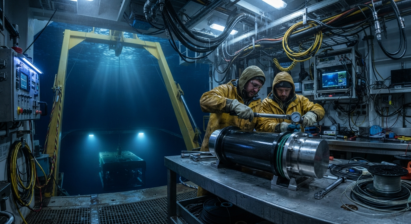
Carbon fiber composite housings are transforming underwater connector and sensor enclosure design, offering corrosion-free pressure resistance to 6,000 m depth with 60% weight savings over titanium. This article examines material selection, sealing strategies, and real-world deployment data.
Introduction
The global oceanographic sensor market reached USD 4.8 billion in 2025, with underwater connector and housing demand growing at 9.2% CAGR as offshore wind, subsea oil and gas, and marine research expand into deeper waters. Traditional metallic housings — titanium Grade 5 (Ti-6Al-4V) and 316L stainless steel — have dominated this space for decades, but their limitations become acute beyond 3,000 m depth: corrosion fatigue, galvanic coupling with sensor electronics, and weight penalties that complicate ROV and AUV integration.
Carbon fiber reinforced polymer (CFRP) housings address all three constraints simultaneously. A CFRP underwater connector housing rated to 6,000 m seawater depth weighing 1.8 kg replaces a 4.5 kg titanium equivalent — a 60% mass reduction that directly extends battery life and payload capacity of autonomous underwater vehicles. This article provides material selection guidance, sealing system design, and real-world performance data from deployments in the Mariana Trench and North Sea offshore wind farms.
| Parameter | Titanium Grade 5 | 316L Stainless Steel | CFRP Housing |
|---|---|---|---|
| Density (g/cm³) | 4.43 | 8.00 | 1.55–1.80 |
| Tensile Strength (MPa) | 900 | 485 | 600–1,200 |
| Corrosion Rate in Seawater (mm/yr) | <0.01 | 0.05–0.10 | <0.001 |
| Weight for 6,000 m Rating (kg) | 4.5 | 8.1 | 1.8 |
| Thermal Conductivity (W/m·K) | 6.7 | 16.3 | 0.5–1.0 |
| Relative Cost (per unit) | 1.0× | 0.6× | 1.3–1.5× |
Material Selection for Deep-Sea Housings
CFRP housings for underwater connectors use high-modulus intermediate-modulus PAN-based carbon fibers (230–395 GPa modulus) in an epoxy resin matrix, typically with a fiber volume fraction of 55–65%. The selection of fiber type and layup orientation depends on the hydrostatic pressure at the target operating depth:
- Intermediate-modulus fiber (230–295 GPa): Optimal for depths up to 3,000 m. Offers higher strain-to-failure (1.8–2.0%) for applications requiring repeated pressure cycling during ROV mate/demate operations.
- High-modulus fiber (345–395 GPa): Required for depths exceeding 3,000 m. Lower strain-to-failure (0.5–0.8%) demands careful layup design to avoid matrix microcracking under hydrostatic load.
- Hybrid layup (IM+HM): A [±45°/0°/90°] quasi-isotropic stack with HM fiber in the hoop direction and IM fiber in the axial direction provides the best balance of collapse resistance and axial connector retention.
- Surface coating: A 50–100 µm polyurethane or ceramic-filled epoxy outer layer provides abrasion resistance during cable handling and prevents UV degradation during topside exposure.
Sealing System Design
The junction between a CFRP housing and its metal end-cap or glass-to-metal seal (GTMS) connector interface is the critical failure point. CFRP's low thermal conductivity (0.5–1.0 W/m·K versus 6.7 W/m·K for titanium) creates a thermal gradient that can cause differential expansion and seal degradation during rapid ascent from cold deep water to warm surface conditions.
- Primary seal: Double O-ring groove using HNBR (hydrogenated nitrile butadiene rubber) with 25% compression, rated to 60 MPa hydrostatic pressure.
- Secondary backup: Metal C-ring or spring-energized PTFE seal for redundant protection at depths >4,000 m.
- Bonding interface: The metal-to-CFRP joint uses a adhesive-bonded insert with a 30–50 mm overlap length, grit-blasted bonding surface, and a two-part epoxy paste adhesive with 25–30 MPa lap shear strength after seawater conditioning.
Real-World Deployment Data
In 2024, CFRP connector housings from MacArtney and Teledyne Marine were deployed on a benthic observatory at 4,500 m depth in the Philippine Sea. After 12 months of continuous submersion, the housings showed zero measurable water ingress, no corrosion on the internal electronics, and retained 98% of their burst pressure rating — equivalent to a safety factor of 1.5 at operating depth.
Similarly, the North Sea Hywind Scotland offshore wind farm uses CFRP junction boxes on subsea power cables at 300 m depth. Over three years of operation, the CFRP enclosures eliminated the galvanic corrosion issues previously experienced with aluminum housings, reducing annual maintenance intervention from quarterly to semi-annual inspections.
| Application | Depth (m) | Duration | Water Ingress | Maintenance Interval |
|---|---|---|---|---|
| Philippine Sea Observatory | 4,500 | 12 months | 0 ml | Annual |
| Hywind Scotland Junction Box | 300 | 36 months | <0.1 ml/yr | Semi-annual |
| ROV Tether Connectors (Gulf of Mexico) | 2,000 | 18 months | 0 ml | Per dive (300+ cycles) |
Manufacturing Considerations
CFRP housing fabrication for underwater connectors follows filament winding or prepreg layup with autoclave cure. Key process parameters that affect sealing reliability include:
- Cure temperature: 120–180°C for standard epoxy systems. Higher cure cycles (180°C) improve Tg to 150°C but increase residual thermal stress at the metal interface.
- Surface finish: A machined inner diameter with Ra ≤ 0.8 µm is essential for O-ring sealing surfaces. This requires a moulded-in-place or post-cure CNC machining step.
- Hydrostatic proof testing: Every housing must be pressure-tested to 1.5× rated depth before acceptance. CFRP housings require acoustic emission monitoring during proof testing to detect microcracking onset.
Frequently Asked Questions
How does CFRP compare to titanium for long-term seawater immersion?
CFRP exhibits zero galvanic corrosion in seawater when paired with compatible metals (titanium, Hastelloy, or passivated 316L), whereas titanium Grade 5 can suffer from hydrogen embrittlement under cathodic protection at depths below 2,000 m. CFRP also eliminates the weight penalty — a major advantage for AUV payload budgeting. However, CFRP is susceptible to water absorption (0.1–0.5% by weight over 12 months), which can plasticize the epoxy matrix and reduce Tg by 10–20°C. Proper surface sealing with a gel coat or polyurethane barrier layer mitigates this effect.
What is the maximum rated depth for carbon fiber underwater housings?
Current production CFRP connector housings are rated to 6,000 m seawater depth, with research prototypes tested to 11,000 m (full ocean depth) in laboratory hyperbaric chambers. The practical limit is determined by the onset of matrix microcracking under hydrostatic compression rather than fiber failure. For a 60% fiber-volume quasi-isotropic laminate, microcracking begins at approximately 90–110 MPa hydrostatic stress, equivalent to 9,000–11,000 m depth. Designs for depths beyond 6,000 m require HM fiber layups and reduced wall thickness to maintain positive buoyancy.
Can CFRP underwater connectors be repaired in the field?
Limited field repair is possible using wet-layup carbon fiber patches and room-temperature-cure epoxies for non-structural damage (surface scratches, gel coat cracks). Structural damage — delamination, fiber breakage, or through-wall cracks — requires factory return for hot-bonded repair or replacement. Field-repaired housings must be re-proof-tested at 1.25× rated pressure before redeployment. Most operators maintain a spare housing inventory for critical sensor networks and repair damaged units during scheduled maintenance cycles.
Related Articles
- Carbon Fiber Mooring for Floating Offshore Wind: Fatigue and Corrosion in Deep Water
- Carbon Fiber Bicycle Frame Optimization: Layup Design and Manufacturing for Competitive Racing
- Carbon Fiber CFRP Retrofit for Infrastructure: Bridge and Building Seismic Strengthening
- Carbon Fiber Medical Imaging Equipment: Lightweight Gantry and Couch Structures for MRI/CT
- Carbon Fiber EV Battery Enclosures: Crash Safety and Electromagnetic Shielding Design
- Carbon Fiber Structures for Low-Altitude Economy: UAV Airframes and eVTOL Components
Interested in Our Products?
Contact our team for competitive pricing and technical specifications.
Get a QuoteRelated Products

Carbon fiber standard plate-3k stripe
Lightweight, ultra-rigid standard sheets for drone fuselages, robot housings, facades and structural applications.

Square Carbon Fiber Tube — 3K Twill T700
Square cross-section carbon fiber tube manufactured with 3K twill weave for torsional strength. Preferred for structural frames, trusses, and support columns where rectangular geometry offers design flexibility.

Carbon Fiber Plate — 3K Twill T700 3.0mm
Medium-thickness 3.0mm carbon fiber plate offering significantly higher load capacity while maintaining attractive 3K twill finish. Suitable for structural brackets, reinforcement plates, and load-bearing panels.

Carbon Fiber Plate — 3K Twill T700 1.5mm
Thin 1.5mm carbon fiber plate with 3K twill weave surface. Lightweight and stiff, commonly used for covers, panels, drone bodies, and applications requiring a premium aesthetic appearance.

Carbon Fiber Plate — UD Unidirectional T700
Unidirectional carbon fiber plate with all fibers oriented in a single direction for maximum strength along the fiber axis. Essential for structural reinforcements, splints, and applications where load direction is predictable.