
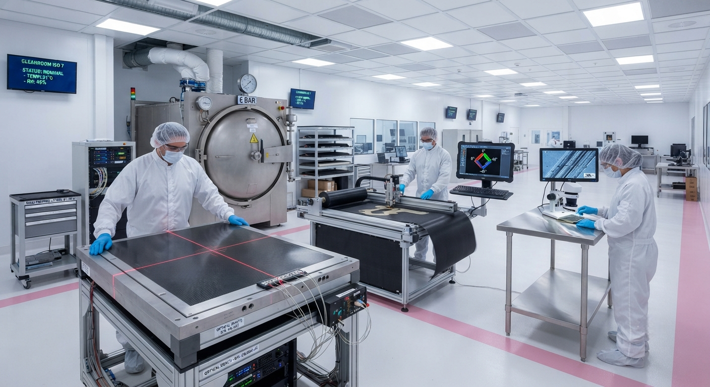
Technical deep dive into carbon fiber optical benches for space telescopes covering CTE engineering, UHM fiber selection, cyanate ester matrices, cryogenic thermal cycling, and case studies of JWST and PLATO.
Carbon Fiber Optical Benches for Space Telescopes: Material Selection and Design Rationale
Space telescope optical benches demand structural materials that combine exceptional dimensional stability — measured in nanometers per degree Kelvin — with high specific stiffness and near-zero moisture expansion in vacuum. Carbon fiber reinforced polymer (CFRP) has emerged as the preferred material for precision optical metering structures in flagship space observatories, including the James Webb Space Telescope (JWST) backplane, the PLATO telescope optical bench, and the Euclid spacecraft's silicon carbide primary mirror support structure. The fundamental advantage of carbon fiber for space optical benches lies in its tailorable coefficient of thermal expansion (CTE), which can be engineered to values below 0.1 ppm/K — approximately one-fiftieth of aluminum's 23 ppm/K and one-tenth of Invar's 1.2 ppm/K. This near-zero CTE enables the optical bench to maintain precise focal plane alignment across the extreme thermal gradients that occur during orbital operations, where a spacecraft may experience temperature differentials of 200°C or more between eclipse and sunlight exposure.
The selection of the carbon fiber precursor and modulus grade is the single most consequential design decision for space optical benches. High-modulus (HM) and ultra-high-modulus (UHM) pitch-based carbon fibers — such as Mitsubishi K13D2U (modulus 935 GPa) and Nippon Graphite Fiber XN-100 (modulus 1,020 GPa) — are preferred for space optical structures due to their negative CTE in the fiber direction, which offsets the positive CTE of the polymer matrix to achieve a near-zero net CTE. The fiber volume fraction (Vf) is typically maintained between 58% and 65% for optical bench laminates, with higher Vf producing lower and more negative axial CTE values. For the JWST backplane — at 6.5 meters in diameter the largest deployable optical bench ever constructed — the prime contractor used M55J carbon fiber (modulus 540 GPa) in a cyanate ester resin matrix, achieving a measured CTE of 0.05 ± 0.10 ppm/K across the operating temperature range of 30 K to 50 K.
| Property | CFRP Optical Bench | Aluminum 6061-T6 | Invar 36 | Silicon Carbide |
|---|---|---|---|---|
| Density (g/cm³) | 1.55–1.65 | 2.70 | 8.05 | 3.21 |
| CTE (ppm/K) at 293 K | −0.1 to +0.3 (tailorable) | 23.6 | 1.2 | 2.4 |
| CTE (ppm/K) at 30–77 K | −0.3 to +0.1 (tailorable) | 11.4 | 0.7 | 0.9 |
| Specific Stiffness (E/ρ × 10⁶ m) | 8.5–12.0 | 2.5 | 1.5 | 10.5 |
| Thermal Conductivity (W/m·K) | 50–350 (fiber direction) | 167 | 10 | 120 |
| Moisture Expansion (με/%RH) | 0.1–0.5 (hermetic coating required) | 0 | 0 | 0 |
| Fatigue Endurance (10⁷ cycles) | 70–80% of ultimate | 30–40% of ultimate | 40–50% of ultimate | Brittle — Weibull stochastic |
| Manufacturing Max Size | Monolithic to 4 m; segmented beyond | Varies by extrusion/forging | Limited by casting size | Sintering limits 1.5 m monolithic |
The matrix resin system for space optical benches must satisfy three competing requirements — vacuum-compatible outgassing below 1% total mass loss (TML) and 0.1% collected volatile condensable materials (CVCM) per ASTM E595, cryogenic temperature survivability without microcracking, and dimensional stability over mission lifetimes spanning 5 to 15 years. Cyanate ester resins have become the industry standard for space optical benches, displacing earlier epoxy systems due to their superior thermal cycling performance and lower moisture absorption. Cyanate esters exhibit TML values of 0.3% to 0.7% and CVCM values below 0.02% — well within the ESA ECSS-Q-ST-70-02C and NASA MSFC-SPEC-1443 requirements. The glass transition temperature (Tg) of cyanate ester systems for optical benches is typically specified at 250°C or higher, ensuring that the resin system remains in the glassy state across the spacecraft thermal envelope. For cryogenic optical benches operating below 100 K, thermoplastic resins such as PEEK and PEKK offer advantages in microcrack resistance, though their higher processing temperatures and tooling costs limit adoption to niche applications.
Manufacturing Processes for Space-Grade Optical Benches
The fabrication of carbon fiber optical benches for space telescopes follows a precisely controlled manufacturing sequence that integrates ply orientation design, autoclave or out-of-autoclave cure, thermal cycling stabilization, precision machining, and hermetic coating application. The laminate stacking sequence is optimized using finite element analysis (FEA) coupled with CTE modeling software to achieve the target quasi-isotropic or tailored anisotropic thermal expansion behavior. Typical space-qualified laminates use quasi-isotropic stacking with 0°, ±45°, and 90° plies in equal proportions, giving an in-plane CTE that is near-zero and uniform in all directions. For structures requiring directional thermal stability — such as optical bench metering arms that must maintain a specific focal length — tailored anisotropic stacking with a predominance of 0° plies in the critical axis direction is employed.
- Ply Cutting and Layup: Automated ply cutting machines (e.g., Gerber Zünd or Lectra systems) process UHM carbon fiber prepreg in class 10,000 ISO 7 cleanrooms to prevent contamination. Ply orientation tolerance is ±1 degree for space optical benches, compared to ±3 degrees for commercial aerospace structures.
- Cure Cycle: Autoclave curing at 180°C to 200°C and 6 to 7 bar pressure for 2 to 4 hours, followed by a freestanding post-cure at 200°C to 250°C for 4 to 8 hours. Temperature ramp rates are restricted to 0.5–1.5°C per minute to minimize thermal gradients within thick laminate sections.
- Thermal Cycling Stabilization: The cured optical bench undergoes 10 to 20 thermal cycles between −196°C (liquid nitrogen) and +150°C to relieve residual stresses and stabilize the microstructure. Each cycle includes a 1-hour dwell at the temperature extremes. Dimensional measurements are taken after every cycle to confirm that the bench is dimensionally stable within ± 2 microns.
- Precision Machining: Diamond-tipped carbide tooling on 5-axis CNC machines with thermal compensation (e.g., DMG MORI DMU series) machines the optical bench to final dimensions. Mounting interfaces for mirrors, sensors, and metering systems are machined to tolerances of ± 5 microns with surface finishes of 0.8 μm Ra or better.
- Hermetic Coating: A thin-film hermetic barrier — typically 3 to 10 microns of aluminum or silicon oxide deposited via physical vapor deposition (PVD) or atomic layer deposition (ALD) — prevents moisture absorption that would otherwise cause hygroscopic expansion of the CFRP in pre-launch conditions.
- Qualification Testing: The completed optical bench undergoes vibration testing (random and sine sweep per MIL-STD-1540 or ECSS-E-ST-10-03), thermal vacuum cycling (TVAC) at ≤ 1×10⁻⁶ torr, and optical metrology verification using laser interferometry to confirm that all optical mounting interfaces remain within tolerance under simulated launch and operational loads.
Case Studies: JWST Backplane and PLATO Optical Bench
The James Webb Space Telescope backplane — a 6.5-meter diameter CFRP structure manufactured by ATK (now Northrop Grumman Space Systems) — represents the most demanding space optical bench application to date. The backplane consists of three segments, each approximately 2.2 meters across, connected by deployable hinges. The structure carries 18 beryllium mirror segments and maintains their relative alignment within 20 nanometers across the operating temperature range. The backplane laminate uses M55J carbon fiber in a 5250-4 cyanate ester resin system, with a total mass of 350 kg — approximately 40% of the mass of an equivalent aluminum structure. The JWST backplane qualification program included 30 thermal cycles from 30 K to 300 K, with dimensional stability verified by photogrammetry and laser metrology.
ESA's PLATO (PLAnetary Transits and Oscillations of stars) mission, scheduled for launch in 2026, employs 26 cameras mounted on a monolithic carbon fiber optical bench 1.8 meters in diameter. The PLATO optical bench — manufactured by Beyond Gravity (formerly RUAG Space) using M60J carbon fiber in a cyanate ester matrix — must maintain the relative alignment of all 26 CCD focal planes within 10 microns across the spacecraft's operating thermal envelope. The bench underwent 15 thermal cycles between −80°C and +100°C during qualification, verifying CTE stability of 0.08 ± 0.15 ppm/K.
Frequently Asked Questions
Why is carbon fiber preferred over Invar for space telescope optical benches?
Carbon fiber offers a density five times lower than Invar (1.6 g/cm³ vs. 8.05 g/cm³) while achieving comparable or superior CTE values through fiber-matrix engineering. For a given optical bench geometry, a CFRP structure weighs 70–80% less than an Invar equivalent. This weight saving enables larger primary mirrors and more instruments within the spacecraft mass budget, or alternatively allows reduced launch vehicle costs. Additionally, CFRP's high specific stiffness provides better dynamic performance (higher natural frequencies) for the same mass, reducing the structural response to launch vibration loads.
How is the coefficient of thermal expansion (CTE) of a carbon fiber optical bench measured?
CTE measurement for space optical benches is performed using high-precision dilatometry or interferometric methods. The most common technique is laser interferometry using a Fizeau or Michelson interferometer with the optical bench as one leg of the interferometer. The optical bench is placed in a thermal vacuum chamber cycled between −196°C and +150°C while a helium-neon laser (633 nm wavelength) measures displacements with sub-micrometer resolution. Measurements are taken at 10°C intervals during both heating and cooling ramps at rates below 1°C per minute. The reported CTE is the secant CTE between two reference temperatures, typically the qualification temperature limits. The measurement uncertainty for space-qualified CTE testing is typically ±0.05 ppm/K.
What causes microcracking in CFRP optical benches and how is it prevented?
Microcracking — the formation of intralaminar or interlaminar cracks in the composite matrix — occurs when thermal stresses exceed the transverse tensile strength of the lamina. This is most acute during cryogenic thermal cycling where the matrix contracts more than the fibers, generating tensile stresses in the matrix. Prevention strategies include: (1) selecting matrix resins with high fracture toughness and low thermal expansion (cyanate ester and thermoplastic resins perform best), (2) optimizing the cure cycle to minimize residual stresses, (3) interleaving thin veils of toughened thermoplastic particles between plies, and (4) limiting ply thickness to 0.05–0.08 mm for cryogenic applications. Space qualification programs typically verify microcrack resistance through 100 to 500 thermal cycles with post-cycle C-scan ultrasonic inspection.
Part of topic
Related Articles
- Carbon Fiber Mooring for Floating Offshore Wind: Fatigue and Corrosion in Deep Water
- Carbon Fiber Bicycle Frame Optimization: Layup Design and Manufacturing for Competitive Racing
- Carbon Fiber CFRP Retrofit for Infrastructure: Bridge and Building Seismic Strengthening
- Carbon Fiber Medical Imaging Equipment: Lightweight Gantry and Couch Structures for MRI/CT
- Carbon Fiber EV Battery Enclosures: Crash Safety and Electromagnetic Shielding Design
- Carbon Fiber Structures for Low-Altitude Economy: UAV Airframes and eVTOL Components
Interested in Our Products?
Contact our team for competitive pricing and technical specifications.
Get a QuoteRelated Products

Carbon fiber standard plate-3k stripe
Lightweight, ultra-rigid standard sheets for drone fuselages, robot housings, facades and structural applications.

Carbon Fiber Plate — 3K Twill T700 3.0mm
Medium-thickness 3.0mm carbon fiber plate offering significantly higher load capacity while maintaining attractive 3K twill finish. Suitable for structural brackets, reinforcement plates, and load-bearing panels.

Carbon Fiber Plate — 3K Twill T700 1.5mm
Thin 1.5mm carbon fiber plate with 3K twill weave surface. Lightweight and stiff, commonly used for covers, panels, drone bodies, and applications requiring a premium aesthetic appearance.

Square Carbon Fiber Tube — 3K Twill T700
Square cross-section carbon fiber tube manufactured with 3K twill weave for torsional strength. Preferred for structural frames, trusses, and support columns where rectangular geometry offers design flexibility.

Carbon Fiber Plate — UD Unidirectional T700
Unidirectional carbon fiber plate with all fibers oriented in a single direction for maximum strength along the fiber axis. Essential for structural reinforcements, splints, and applications where load direction is predictable.