
Every spacecraft that generates power from sunlight depends on a solar array — and on the substrate that carries, protects, and aligns the photovoltaic cells. Over the past two decades, the rigid panel substrate has converged on a single dominant architecture: a sandwich panel with carb
Introduction
Every spacecraft that generates power from sunlight depends on a solar array — and on the substrate that carries, protects, and aligns the photovoltaic cells. Over the past two decades, the rigid panel substrate has converged on a single dominant architecture: a sandwich panel with carbon fiber composite facesheets bonded to an aluminum honeycomb core. The combination wins because it delivers extreme stiffness-to-mass ratios, near-zero coefficient of thermal expansion (CTE) in the plane of the panel, and proven stability in the vacuum and radiation environment of space.
For engineers selecting substrate materials for a new satellite program, the design problem is not weight alone. The panel must keep photovoltaic cells flat and aligned while the spacecraft swings from direct sunlight into shadow, cycling through temperature swings of 200 degrees or more on every orbit. It must survive launch vibration, resist radiation-induced property degradation over a 15-20 year mission, and support deployment mechanisms that unfold the array in a single, reliable motion. This article walks through the material selection logic and manufacturing routes that meet these demands.
Why Rigid Panels Use Sandwich Construction
The solar array substrate is a bending-dominated structure: it spans between the deployment hinges and must react the substantial inertia loads of hundreds of kilograms of photovoltaic cells during launch, then hold its shape against thermal gradients on orbit. Sandwich construction — two thin, stiff facesheets separated by a lightweight core — maximizes bending stiffness per unit mass by placing the strong material at the surfaces where bending stresses are highest.
- Facesheets: Typically 1-2 mm of carbon fiber reinforced polymer (CFRP), laid up in a quasi-isotropic or orthotropic pattern to balance in-plane stiffness in both panel directions.
- Core: Aluminum honeycomb, typically 3/16-1 inch cell size, chosen for its strength, low density, and predictable compression properties.
- Adhesive bonding: Structural film adhesives bond facesheet to core; the bondline quality dominates the panel's structural integrity and is the focus of NDT inspection.
Compared with a solid aluminum panel of equal bending stiffness, a CFRP-honeycomb sandwich is typically 30-50% lighter — and weight in solar arrays is exponentially expensive, because every kilogram at the array tip multiplies through the deployment mechanism, the panel drive assembly, and the spacecraft bus.
Material Selection: CTE, Stiffness, and Radiation Resistance
Three material properties drive the choice between CFRP and aluminum facesheets. The first is coefficient of thermal expansion: aluminum expands at roughly 23 ppm/°C, while CFRP in-plane CTE can be tuned to near zero or even slightly negative by balancing fiber orientation. In a panel several meters long, a 200-degree temperature swing would distort an aluminum panel by several millimeters — enough to misalign cells, load the hinges, and shift the array's center of mass. CFRP stays within fractions of a millimeter.
The second property is stiffness-to-mass ratio. High-modulus carbon fiber offers in-plane modulus of 290-395 GPa with a density of 1.8 g/cm³, versus 70 GPa for aluminum — roughly five times the specific stiffness. This is what allows a 5-meter panel to maintain its deployed flatness against thermal and inertia loads with a facesheet only 1-2 mm thick.
The third is radiation resistance. CFRP does not suffer the significant loss of mechanical properties that polymer matrices experience under extended exposure to ionizing radiation; the concern is instead the polymer matrix, which requires proper selection of the resin system. Polycyanate and polyimide-based systems are favored where radiation doses are high, because epoxy can degrade after high accumulated doses. The table below summarizes the prevailing substrate options:
| Facesheet material | In-plane CTE (ppm/°C) | Modulus (GPa) | Density (g/cm³) | Radiation behavior |
|---|---|---|---|---|
| Aluminum 6061 | 23.4 | 70 | 2.7 | Metallurgically stable; thermal distortion dominates |
| Standard-modulus CFRP (T700-class) | ±0.5 to 1.0 (tuned) | 230 | 1.8 | Exposure-resistant with appropriate resin |
| High-modulus CFRP (M55J-class) | -0.3 to 0.3 (tuned) | 295-395 | 1.8 | Lower strain-to-failure; needs careful design |
| Titanium | 8.6 | 113 | 4.5 | Stable but heavy; used for fittings only |
In practice, most rigid-panel programs select high-modulus or intermediate-modulus CFRP facesheets to reach the necessary CTE tuning and stiffness, accepting the higher material cost because the mass saving — and therefore the launch-cost saving — dominates the total system economics.
Thermal Design on Orbit and the CTE Story
The thermal environment of a solar array is extreme. On the sunlit side of an orbit the panel's photovoltaic cells absorb intense solar irradiance of roughly 1,370 W/m², warming the panel; in eclipse the panel cools dramatically. The result is a temperature cycle on every orbit, with panel temperatures ranging from around minus 100 degrees to plus 120 degrees Celsius depending on orbit and orientation.
If the substrate expands and contracts as it heats and cools, several problems arise: photovoltaic cells and their interconnects experience cyclic strain that can fatigue solder joints; the panel curvature changes, altering the angle of incidence of sunlight and reducing power output; and the deployment structure receives cyclic loads that it must survive for 20-plus years. Near-zero CTE CFRP facesheets limit panel thermal strain to a few hundredths of a percent over the full temperature range — small enough that cell-interconnect fatigue and power loss become negligible. This is the central reason CFRP, rather than aluminum, has become the standard material for large rigid solar array panels.
Manufacturing and Qualification Considerations
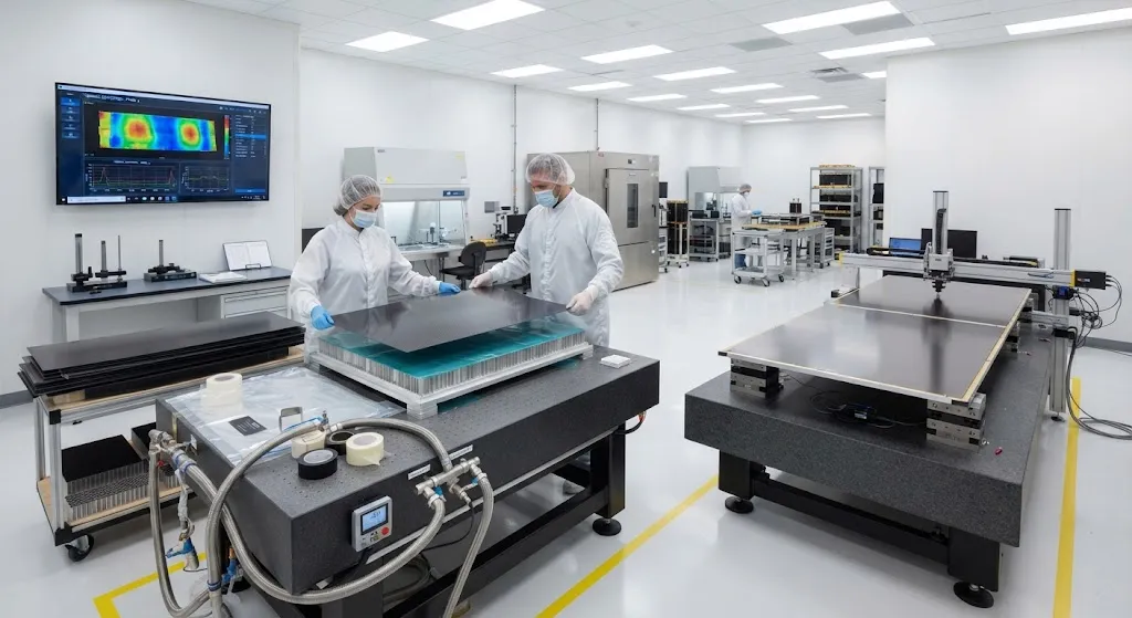
Rigid CFRP solar array substrates are manufactured by laminating facesheets in an autoclave or by out-of-autoclave cure, then bonding to the honeycomb core in a second step with film adhesive under vacuum and heat. Facesheets for high-performance panels are often cured as flat panels and inspected for porosity via ultrasonic scanning before core bonding; voids above roughly 1% in the facesheet laminate are unacceptable for space structures because they degrade both strength and vacuum stability.
Mechanical testing for space qualification follows a standard sequence: coupon-level testing of the facesheet laminate (tensile, compression, and interlaminar shear), panel-level testing including flatwise tension and shear through the bonded core, and finally sine and random vibration testing of the full array panel to simulate launch loads, typically with a qualification margin of 1.5x or more on the expected flight environment.
Several manufacturing details matter for the final product:
- CTE verification: Measuring the facesheet's actual in-plane CTE by interferometry or strain-gauge techniques over the flight temperature range, because the tuned value depends on the precise fiber volume fraction and layup actually cured.
- Moisture control: Polymer matrices absorb moisture that outgasses in vacuum, causing dimensional change; panels are dried and baked out before final assembly and kept dry through integration.
- Deployment hinge alignment: The substrate must hold hinge positions within tight tolerances; photogrammetry or laser tracker measurement of the assembled panel verifies flatness and hinge-line straightness.
Frequently Asked Questions
Why not simply use aluminum for the entire solar array substrate?
Aluminum facesheets are inexpensive, easy to manufacture, and metallurgically stable in space, and they were used on many early spacecraft. The problem is twofold. First, aluminum's CTE of roughly 23 ppm/°C causes multi-millimeter thermal distortion in a multi-meter panel across the orbital temperature swing, which fatigues cell interconnects and reduces power output. Second, aluminum's specific stiffness is about five times lower than high-modulus CFRP, so a stiffness-equivalent aluminum panel is significantly heavier. Once payload cost per kilogram is factored in, CFRP facesheets win on the system-level trades even though the raw material is far more expensive.
Does radiation actually degrade carbon fiber composites in orbit?
Carbon fiber itself is essentially unaffected by the ionizing radiation environment of Earth orbit — the fibers retain their strength and modulus over mission lifetimes. The polymer matrix is the vulnerable component: prolonged exposure to high radiation doses can break polymer chains, embrittle the resin, and reduce its glass transition temperature. The standard mitigations are to select radiation-tolerant resin systems (polycyanate or polyimide families), keep the matrix content and void content low, and verify matrix property retention through testing at accumulated mission-dose fluences. For geostationary and LEO missions with typical shielding, these measures keep CFRP facesheets well within qualification.
What margin exists before CFRP facesheets get brittle from space exposure?
Spacecraft design practices typically require that the facesheet retain at least 60-80% of its initial mechanical properties at end of life, and qualification testing demonstrates this at doses accumulated to 1.5-2x the expected mission fluence. Because carbon fiber carries the vast majority of the load in the fiber direction, and fiber properties do not degrade, the panel's primary structure retains its stiffness even as the matrix somewhat embrittles. The risk is concentrated in matrix-dominated properties — transverse strength, interlaminar shear, and transverse cracking — which is why resin system selection and post-cure optimization are critical in the design trade.
Conclusion
The rigid composite solar array substrate is a textbook demonstration of why carbon fiber dominates spacecraft structures: near-zero tunable CTE, extreme specific stiffness, and radiation-tolerant behavior together produce the lightest panel that reliably generates power across a 15-20 year mission in a punishing thermal cycle. The sandwich architecture with CFRP facesheets and aluminum honeycomb core has become the industry standard, and the design logic — bending-efficient sandwich, CTE-tuned facesheets, controlled matrix systems — applies equally to the next generation of flexible and large-area arrays.
For satellite and spacecraft teams selecting substrate materials, the critical early decisions are facesheet fiber grade (standard versus high modulus), resin system selection for radiation tolerance, and CTE verification planning. Explore our carbon fiber composite materials for aerospace and space structures, or contact our engineering team to discuss facesheet material selection and qualification for your space program.
Part of topic
Related Articles
- Carbon Fiber Mooring for Floating Offshore Wind: Fatigue and Corrosion in Deep Water
- Carbon Fiber Bicycle Frame Optimization: Layup Design and Manufacturing for Competitive Racing
- Carbon Fiber CFRP Retrofit for Infrastructure: Bridge and Building Seismic Strengthening
- Carbon Fiber Medical Imaging Equipment: Lightweight Gantry and Couch Structures for MRI/CT
- Carbon Fiber EV Battery Enclosures: Crash Safety and Electromagnetic Shielding Design
- Carbon Fiber Structures for Low-Altitude Economy: UAV Airframes and eVTOL Components
Interested in Carbon Fiber Tubes?
Contact our team for competitive pricing and technical specifications.
Get a Quote