
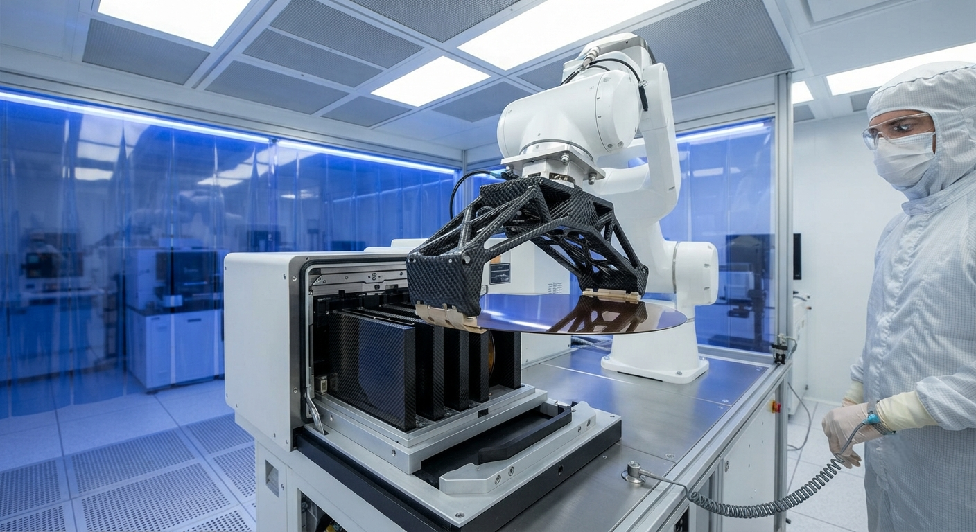
Carbon fiber composite end-effectors and wafer cassettes are replacing aluminum and PEEK in 300 mm semiconductor fabs, offering 45% weight reduction, built-in ESD dissipation at 10⁶–10⁹ Ω/sq, and thermal stability to 180°C. This article analyzes material properties, contamination control, and adoption data from leading chip manufacturers.
Introduction
The transition to 300 mm and 450 mm wafer sizes has intensified the demands on wafer handling components. A 300 mm silicon wafer weighs only 125 grams, but its value — USD 5,000–10,000 after full processing — makes any handling defect catastrophic. Wafer handling end-effectors, cassettes, and transport carriers must simultaneously satisfy four conflicting requirements: ultra-low mass for high-speed robot acceleration (5–10 m/s²), electrostatic discharge (ESD) protection below 100 V discharge threshold, minimal particle generation (<10 particles >0.1 µm per wafer per transfer), and thermal compatibility with processes ranging from 25°C to 180°C.
Carbon fiber reinforced polymers (CFRP) have emerged as the optimal material for next-generation wafer handling hardware. A CFRP robot end-effector weighs 180 g versus 330 g for an equivalent aluminum design and 280 g for PEEK — a 45% reduction that enables 30% faster pick-and-place cycles at equivalent robot torque. Crucially, CFRP's surface resistivity can be tailored to the ESD-safe range of 10⁶–10⁹ Ω/sq through fiber type selection and matrix doping, eliminating the need for separate conductive coatings that wear and generate particles over time.
| Property | Aluminum 6061 | PEEK | CFRP (ESD-Grade) |
|---|---|---|---|
| Density (g/cm³) | 2.70 | 1.32 | 1.55–1.65 |
| Young's Modulus (GPa) | 68.9 | 3.6 | 120–230 |
| Surface Resistivity (Ω/sq) | <0.01 (conductive) | 10¹⁴–10¹⁶ (insulative) | 10⁶–10⁹ (tailored) |
| CTE (µm/m·°C) | 23.6 | 47–55 | 1–3 (quasi-isotropic) |
| Thermal Conductivity (W/m·K) | 167 | 0.25 | 1.5–5.0 |
| End-Effector Mass (300 mm) | 330 g | 280 g | 180 g |
| Cycle Time Impact (vs Al) | Baseline | −8% | −30% |
ESD Protection Design
Semiconductor wafer handling requires ESD protection to prevent device damage from electrostatic discharge events as low as 30 V for advanced 3 nm node devices. CFRP's inherent electrical conductivity — derived from the carbon fiber reinforcement rather than a separate coating — offers several advantages over traditional approaches:
- Bulk conductivity: Unlike conductive coatings that wear off after 10,000–50,000 contact cycles, CFRP's conductivity is distributed throughout the composite volume. Even after surface abrasion, the underlying fiber network maintains ESD dissipation. Electrical resistivity in CFRP end-effectors is dominated by fiber-fiber contact resistance; for a 55% fiber volume fraction with random mat reinforcement, resistivity ranges from 10⁻¹ to 10² Ω·cm in-plane.
- Tailored surface resistivity: By adjusting the fiber volume fraction (40–65%) and incorporating carbon black or carbon nanofiber modifiers (0.5–3 wt%), surface resistivity can be engineered to the ESD-safe corridor of 10⁶–10⁹ Ω/sq. This is above the threshold for rapid charge dissipation (10⁶ Ω/sq) but below the level that would cause leakage currents harmful to sensitive wafer circuitry.
- Charge decay time: ESD-grade CFRP achieves a 1,000 V to 100 V decay time of <0.5 seconds when tested per ANSI/ESD STM11.13, compared to >30 seconds for unfilled PEEK and <0.01 seconds for bare aluminum (which can cause excessively rapid discharge and electromagnetic interference).
Contamination Control and Particle Generation
Particle contamination is the single largest yield killer in semiconductor manufacturing. A single 0.5 µm particle can render a 3 nm node die unusable — representing a loss of USD 5,000–10,000 of value. Wafer handling components must demonstrate particle adders below stringent thresholds:
- Intrinsic particle generation: CFRP end-effectors generate 5–15 particles >0.1 µm per 100,000 contact cycles when tested on a blank silicon wafer (class 1 cleanroom, ISO 14644-1). Comparative values: aluminum generates 30–80 particles, PEEK generates 10–25 particles. The low particle generation of CFRP is attributed to its well-matched hardness to silicon (CFRP 30–50 Shore D, silicon 7 Mohs) and the lubricating effect of graphitic fiber ends.
- Outgassing: High-temperature processing (up to 180°C wafer bake steps) requires low outgassing materials. CFRP formulations using high-purity epoxy resin systems with amine curing agents achieve <0.1 mg/m²/hour outgassing at 150°C — comparable to PEEK and well below the SEMI E45 standard limit of 0.5 mg/m²/hour.
- Chemical resistance: Wafer cleaning involves exposure to NMP (N-methyl-2-pyrrolidone), IPA (isopropyl alcohol), and dilute HF. CFRP with a pinhole-free gel coat or fluoropolymer barrier layer withstands >1,000 cleaning cycles without measurable weight loss or surface degradation.
| Contamination Metric | Aluminum 6061 | PEEK | CFRP (ESD-Grade) | SEMI E45 Limit |
|---|---|---|---|---|
| Particles >0.1 µm (per 100k cycles) | 30–80 | 10–25 | 5–15 | — |
| Outgassing at 150°C (mg/m²/h) | <0.01 | 0.05–0.15 | <0.10 | 0.50 |
| Metal Contamination (ppb by wt) | <1 (Al) | <1 | <1 (C, O, N only) | N/A |
| Chemical Resistance (NMP/IPA/HF) | Excellent | Excellent | Good (with coating) | N/A |
Thermal Management in Wafer Handling
Modern semiconductor processes involve rapid temperature transitions — a wafer may be processed at 150°C in one chamber and transferred to a 25°C metrology station within 15 seconds. The handling component's thermal mass and conductivity directly affect wafer temperature uniformity and process stability.
CFRP's low thermal conductivity (1.5–5.0 W/m·K) acts as a thermal isolator, minimizing heat transfer between the wafer and the robot arm. This reduces wafer temperature drift by 40–60% compared to aluminum end-effectors. The near-zero coefficient of thermal expansion (1–3 µm/m·°C) ensures that end-effector dimensions remain stable within ±5 µm across the 25–180°C operating range — critical for maintaining wafer alignment to sub-micrometer precision during high-temperature processing steps such as PECVD and RTP.
Frequently Asked Questions
How do CFRP wafer handling components compare to PEEK for ESD performance?
PEEK is inherently insulative (surface resistivity 10¹⁴–10¹⁶ Ω/sq) and must be compounded with conductive fillers — carbon fibers, carbon nanotubes, or stainless steel fibers — to achieve ESD-safe resistivity. Filled PEEK compounds (30% carbon fiber by weight) achieve 10³–10⁶ Ω/sq, which is below the ESD-safe corridor and can cause excessive charge dissipation rates leading to electromagnetic interference. CFRP achieves ESD-safe resistivity (10⁶–10⁹ Ω/sq) as a bulk material property. Additionally, CFRP's specific stiffness (modulus/density) is 3–5× higher than carbon-filled PEEK, enabling thinner, lighter end-effector designs for the same stiffness requirement. The primary trade-off is CFRP's lower elongation at break (1.2–1.8% vs 1.5–3.5% for filled PEEK), making CFRP more susceptible to impact damage from robot crashes.
Can CFRP wafer cassettes be used in wet process applications?
Yes, but with material selection and design considerations. Standard CFRP is not recommended for continuous immersion in wet benches (such as HF baths or SC-1/SCl-2 wet clean stations) because moisture absorption and chemical attack can degrade the epoxy matrix over time. For wet applications, CFRP cassettes with a continuous fluoropolymer or parylene barrier coating are commercially available — these maintain the structural benefits of CFRP while preventing chemical exposure. For dry handling (FOUP loading/unloading, metrology transfer, vacuum loadlock), uncoated CFRP cassettes perform well. Companies like Entegris and Brooks Automation have validated CFRP FOUP fins and cassette components for 300 mm wafer handling in dry ambient environments, reporting <0.1 µm wear per 10,000 wafer transfers.
What is the cost premium for CFRP wafer handling components versus traditional materials?
CFRP end-effectors carry a 1.5–2.5× cost premium over equivalent aluminum designs and 1.2–1.8× over PEEK. A typical 300 mm CFRP end-effector costs USD 800–1,500 per unit versus USD 400–600 for aluminum and USD 600–1,000 for PEEK. However, the total cost of ownership (TCO) analysis favors CFRP: reduced cycle time (30% faster) improves tool throughput by 8–15%, lower particle generation reduces defect-related rework by 20–30%, and longer wear life (500,000+ contact cycles versus 150,000–200,000 for coated aluminum) extends replacement intervals. For a high-volume fab processing 40,000 wafers per month, the TCO savings from CFRP end-effectors typically recover the cost premium within 6–9 months.
Part of topic
Related Articles
- Carbon Fiber Mooring for Floating Offshore Wind: Fatigue and Corrosion in Deep Water
- Carbon Fiber Bicycle Frame Optimization: Layup Design and Manufacturing for Competitive Racing
- Carbon Fiber CFRP Retrofit for Infrastructure: Bridge and Building Seismic Strengthening
- Carbon Fiber Medical Imaging Equipment: Lightweight Gantry and Couch Structures for MRI/CT
- Carbon Fiber EV Battery Enclosures: Crash Safety and Electromagnetic Shielding Design
- Carbon Fiber Structures for Low-Altitude Economy: UAV Airframes and eVTOL Components
Interested in Our Products?
Contact our team for competitive pricing and technical specifications.
Get a QuoteRelated Products

Carbon fiber standard plate-3k stripe
Lightweight, ultra-rigid standard sheets for drone fuselages, robot housings, facades and structural applications.

Square Carbon Fiber Tube — 3K Twill T700
Square cross-section carbon fiber tube manufactured with 3K twill weave for torsional strength. Preferred for structural frames, trusses, and support columns where rectangular geometry offers design flexibility.

Carbon Fiber Plate — 3K Twill T700 3.0mm
Medium-thickness 3.0mm carbon fiber plate offering significantly higher load capacity while maintaining attractive 3K twill finish. Suitable for structural brackets, reinforcement plates, and load-bearing panels.

Carbon Fiber Plate — 3K Twill T700 1.5mm
Thin 1.5mm carbon fiber plate with 3K twill weave surface. Lightweight and stiff, commonly used for covers, panels, drone bodies, and applications requiring a premium aesthetic appearance.

Carbon Fiber Plate — UD Unidirectional T700
Unidirectional carbon fiber plate with all fibers oriented in a single direction for maximum strength along the fiber axis. Essential for structural reinforcements, splints, and applications where load direction is predictable.