
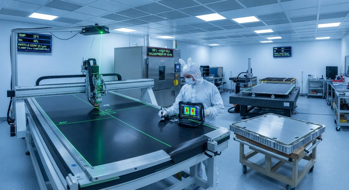
A technical analysis of carbon fiber composite substrates for satellite solar panels — examining specific stiffness requirements, thermal stability in LEO/GEO environments, honeycomb panel construction, deployment hinge integration, and qualification testing standards for B2B buyers in the space ind
Introduction: The Structural Foundation of Space Solar Power
Every satellite in orbit — from 3U CubeSats weighing 5 kg to 6,000 kg geostationary communications platforms — depends on its solar array for electrical power. The solar panel substrate, upon which photovoltaic cells are bonded and which must survive launch vibration, orbital thermal cycling, and deployment shock, is almost exclusively manufactured from carbon fiber reinforced polymer composites in modern spacecraft. The substrate must simultaneously meet contradictory requirements: maximum stiffness for minimum mass, near-zero coefficient of thermal expansion (CTE) to prevent cell cracking across temperature swings of ±150°C, and sufficient strength to withstand the deployment mechanism's kinematic loads.
This article provides a technical overview of carbon fiber solar panel substrate design for B2B buyers in the satellite and space systems industry — covering material selection, honeycomb panel construction, stiffness and thermal design parameters, deployment hinge integration, and the qualification standards that govern substrate procurement.
Material Selection: Fiber and Resin for Space Applications
The choice of carbon fiber and resin system for solar panel substrates is driven by three dominant requirements: specific stiffness (modulus divided by density), dimensional stability across a wide temperature range, and resistance to the space environment (vacuum, ultraviolet radiation, atomic oxygen in LEO).
| Property | Standard Modulus (T300-class) | Intermediate Modulus (T800-class) | High Modulus (M55J-class) | Ultra-High Modulus (K13D-class) |
|---|---|---|---|---|
| Tensile Modulus (GPa) | 230 | 295 | 540 | 935 |
| Tensile Strength (MPa) | 3,530 | 5,880 | 3,920 | 3,730 |
| Density (g/cm³) | 1.76 | 1.80 | 1.91 | 2.18 |
| Specific Modulus (10⁶ m²/s²) | 131 | 164 | 283 | 429 |
| CTE (×10⁻⁶ /°C, longitudinal) | −0.4 | −0.6 | −1.0 | −1.5 |
| Filament Diameter (µm) | 7.0 | 5.0 | 4.2 | 10.0 |
| Relative Cost | 1.0× | 2.0–3.0× | 5.0–8.0× | 15–25× |
| Typical Space Use | Small sat, CubeSat | Medium LEO sat | GEO comm sat | Optical bench, high-stability |
For the resin matrix, space-grade epoxy systems with low outgassing properties (total mass loss <1.0%, collected volatile condensable material <0.1% per ASTM E595) are standard. Cyanate ester resins are used for the most demanding optical-grade substrates where zero CTE and minimal moisture absorption are critical. BMI resins appear in substrate designs requiring higher temperature capability during deployment (e.g., for solar arrays on Venus or Mercury missions).
Honeycomb Panel Construction: The Sandwich Approach
Solar panel substrates almost universally employ a sandwich construction: two thin carbon fiber face sheets bonded to a lightweight honeycomb core. This configuration provides the bending stiffness required to resist launch acceleration loads (typically 8–15g in the in-plane direction, 15–30g in the out-of-plane direction) while maintaining the lowest possible areal density.
Typical construction parameters for a GEO communications satellite solar panel substrate (2.5 m × 1.5 m panel):
- Face sheets: 3–5 plies of high-modulus carbon fiber/epoxy prepreg, [0/90/+45/−45]s quasi-isotropic layup. Individual ply thickness 0.125–0.150 mm. Total face sheet thickness 0.375–0.750 mm per side.
- Core material: Aluminum honeycomb, 3.2–6.4 mm cell size, 19–48 kg/m³ density. Alternatively, Nomex® aramid honeycomb (29–64 kg/m³) for non-conductive substrates or where thermal isolation between face sheets is desired.
- Core thickness: 15–35 mm for primary solar panels on GEO satellites; 8–15 mm for LEO small satellite panels.
- Total panel areal density: 1.8–3.5 kg/m² for GEO panels; 1.2–2.0 kg/m² for LEO panels.
- Adhesive: Film adhesive (e.g., Henkel Hysol EA 9696 or Solvay AF 163-2), 0.10–0.25 mm bondline thickness, cured at 120–180°C under vacuum or autoclave pressure.
The quasi-isotropic layup of the face sheets ensures near-isotropic in-plane stiffness (typically E_xy = 50–70 GPa for high-modulus face sheets) and minimizes CTE mismatch with the solar cells, which have a CTE of 2.6–4.0 × 10⁻⁶ /°C for silicon cells and 1.5–2.5 × 10⁻⁶ /°C for multi-junction III-V cells (GaAs, InGaP).
Thermal Stability: Surviving 30,000 Thermal Cycles
A satellite in low Earth orbit (LEO) experiences approximately 15–16 sunlit-to-eclipse transitions per day, each producing a temperature swing of ±100–150°C on the solar panel surface. Over a typical 5-year LEO mission, the panel endures 27,000–29,000 thermal cycles. Geostationary (GEO) satellites experience fewer cycles (90–100 per year for 15 years = 1,350–1,500 cycles) but with larger temperature swings (up to ±170°C) during eclipse seasons.
The critical thermal design requirement is maintaining the solar cell operating temperature within its specified range (typically −80°C to +120°C for silicon cells, −100°C to +150°C for multi-junction cells) while preventing CTE-driven stress at the cell-to-substrate bondline. The substrate's in-plane CTE is engineered by adjusting the fiber orientation and selecting fibers with appropriate longitudinal CTE. A typical optimized substrate achieves an in-plane CTE of 0.5–2.0 × 10⁻⁶ /°C in the panel plane, closely matching the solar cell CTE.
| Parameter | LEO SmallSat Panel | LEO Constellation Panel | GEO Comsat Panel | Deep Space Panel |
|---|---|---|---|---|
| Panel size (typical) | 0.5 × 0.3 m | 1.5 × 0.8 m | 2.5 × 1.5 m | 3.0 × 2.0 m |
| Thermal cycles (mission life) | 25,000–30,000 | 25,000–30,000 | 1,350–1,500 | 500–5,000 |
| Temperature range (°C) | −80 to +110 | −80 to +120 | −140 to +130 | −180 to +150 |
| Max substrate CTE (×10⁻⁶/°C) | 2.0 | 1.5 | 1.0 | 0.5 |
| Minimum natural frequency (Hz) | 50 | 35 | 25 | 20 |
| Radiation dose (krad, Si) | 50–100 | 50–150 | 200–500 | 500–5,000 |
| Typical fiber grade | IM (T800) | HM (M55J) | HM (M55J/M60J) | UHM (K13D) |
Deployment Mechanism Integration
The solar panel substrate must interface with the deployment mechanism — typically a motor-driven hinge or spring-actuated deployment assembly — through embedded metallic inserts or localized reinforced zones. The deployment mechanism imposes several structural requirements on the substrate:
- Hinge bracket interface: The substrate-to-hinge connection is typically made through titanium or Invar inserts bonded into the honeycomb core during panel fabrication. Each hinge point must withstand 200–500 N in the deployment direction and 100–300 N in the preload direction. Insert pull-out strength for a standard 8 mm titanium insert in a 25 mm thick honeycomb panel ranges from 1,500–3,000 N.
- Deployment shock resistance: The shock load when the panel reaches its fully deployed position and the latch mechanism engages can reach 500–2,000g for spring-deployed arrays. The substrate edge and hinge bracket area must be reinforced with additional face sheet plies (6–10 plies locally) to prevent delamination at the hinge interface.
- Hold-down and release: During launch, solar panels are folded and held against the satellite body by hold-down mechanisms — typically pyrotechnic or non-pyrotechnic release devices (melt-wire, paraffin actuator, or shape memory alloy). The substrate must include reinforced hardpoints at each hold-down location, typically 4–12 points per panel. Each hardpoint must withstand 1,000–5,000 N compression load during launch vibration.
- Electrical grounding: The carbon fiber substrate must provide a conductive path for electrostatic discharge (ESD) grounding. This is achieved through either (a) a conductive surface ply (aluminum- or copper-coated carbon fiber fabric), (b) embedded copper foil strips (0.035–0.070 mm thick, 10–25 mm wide) co-cured with the face sheet, or (c) conductive film adhesive in the bondline. Grounding resistance from any point on the panel to the spacecraft ground must be <1 Ω.
Qualification and Acceptance Testing
Carbon fiber solar panel substrates procured for space applications must pass a comprehensive qualification test program before flight acceptance. Key tests include:
- Thermal vacuum cycling: 8–20 cycles at panel-level in a thermal vacuum chamber (pressure < 1.3 × 10⁻³ Pa) over the full operating temperature range. Temperature rate of change controlled at 2–5°C/min. No delamination, cell cracking, or bondline failure is permitted.
- Sine and random vibration: Qualification levels typically 1.25× the predicted flight levels, applied in all three axes. Sine sweep 5–100 Hz at 0.5–2.0g; random vibration 8–20 g_rms over 20–2,000 Hz. The substrate's first natural frequency must exceed the launch vehicle's minimum requirement (typically 20–50 Hz).
- Shock test: Pyrotechnic shock simulation at qualification levels (typically 1,000–5,000g at 1–10 kHz). Accelerometers mounted at the hinge points and panel corners verify shock response.
- Adhesive bond strength: Flatwise tensile testing per ASTM C297 on witness coupons — minimum 3.5 MPa for face sheet-to-core bond; minimum 5.0 MPa for insert bond strength.
- Outgassing: Per ASTM E595 — total mass loss (TML) < 1.0%, collected volatile condensable material (CVCM) < 0.1%.
Frequently Asked Questions
Why is carbon fiber preferred over aluminum for satellite solar panel substrates?
Three fundamental advantages drive the preference: (1) Specific stiffness — carbon fiber substrates achieve specific stiffness (modulus/density) values of 130–430 × 10⁶ m²/s² compared to 25–26 × 10⁶ m²/s² for aluminum alloys. This means a carbon fiber substrate can be 5–16× stiffer than an aluminum substrate of the same mass, or 60–80% lighter for the same stiffness. (2) Thermal stability — carbon fiber laminates can be engineered to a near-zero CTE (0.5–2.0 × 10⁻⁶ /°C in-plane), while aluminum has a CTE of 23.6 × 10⁻⁶ /°C. The CTE mismatch between an aluminum substrate (23.6 × 10⁻⁶ /°C) and a silicon solar cell (2.6–4.0 × 10⁻⁶ /°C) would produce thermal stresses exceeding 30 MPa at a 150°C temperature swing — sufficient to crack the cell or debond the cell-to substrate adhesive within hundreds of cycles. (3) Fatigue resistance — carbon fiber composites do not exhibit conventional fatigue failure in the fiber-dominated direction; their fatigue endurance in the in-plane direction approaches 70–80% of ultimate strength over 10⁷ cycles, compared to 30–50% for aluminum alloys. For LEO constellations requiring 30,000 thermal cycles, this fatigue advantage translates directly to longer panel service life and reduced risk of cell interconnect failures.
What honeycomb core material is best for satellite solar panel substrates?
The choice depends on mission requirements. Aluminum honeycomb (5056 alloy or 3003 alloy, 3.2–6.4 mm cell size, 19–48 kg/m³ density) is the most common — it offers the best strength-to-weight ratio, provides electrical conductivity for ESD grounding, and has decades of flight heritage. For panels requiring thermal isolation between the front and back face sheets (e.g., when the back face must stay below a certain temperature for radiator function), Nomex aramid honeycomb (29–64 kg/m³) offers 3–5× lower thermal conductivity than aluminum honeycomb but adds cost and requires separate ESD grounding. For the lightest panels, carbon fiber honeycomb (8–32 kg/m³) is used on some high-performance GEO satellites, but at 10–20× the cost of aluminum honeycomb. A practical guideline: for LEO constellation panels where cost per watt is critical, aluminum honeycomb with a cell size of 4.8 mm and density of 32 kg/m³ provides the best balance of performance and cost.
How are solar cells bonded to the carbon fiber substrate?
Solar cell-to-substrate bonding uses a multi-layer adhesive system. First, a dielectric isolation layer (typically 25–50 µm Kapton or polyimide film, or a 50–75 µm fiberglass/epoxy ply) is bonded to the substrate face sheet to prevent galvanic corrosion between the carbon fiber (cathodic) and the solar cell metallization (anodic). Then, the solar cells are bonded using a silicone adhesive (e.g., Dow Corning 93-500 or NuSil CV-2568) applied at 100–200 µm thickness after de-airing under vacuum. The silicone adhesive provides CTE strain relief — its modulus (2–8 MPa) is orders of magnitude lower than the cell or substrate, allowing the CTE mismatch to be accommodated by elastic deformation of the adhesive layer rather than stress transfer to the fragile cell. After cell placement, a cover glass (typically 100–150 µm cerium-doped borosilicate) is bonded to the cell front surface using a UV-transparent silicone adhesive. The entire assembly — cover glass + cell + adhesive + substrate — undergoes thermal cycling qualification to verify that no cell cracking or adhesive debonding occurs over the mission life.
What is the typical lead time and cost for a custom satellite solar panel substrate?
For a custom GEO communications satellite panel substrate (2.5 m × 1.5 m, high-modulus fiber, aluminum honeycomb core, with embedded metallic inserts at 12 hinge points), typical lead time is 16–24 weeks from design freeze to delivery. Cost breakdown: engineering and design $15,000–$30,000; tooling (cure fixture, insert alignment jig, bond fixture) $25,000–$60,000; materials (carbon fiber prepreg, honeycomb, film adhesive, inserts) $8,000–$18,000; fabrication (layup, cure, NDT) $20,000–$40,000; qualification testing (thermal vacuum, vibration, shock) $35,000–$75,000. Total program cost range: $105,000–$225,000 per substrate design, with recurring unit cost of $18,000–$35,000 per panel for a production run of 5–10 units. For LEO constellation panels (simpler design, smaller size, standard modulus fibers), costs are significantly lower — total non-recurring $30,000–$60,000, recurring $4,000–$10,000 per panel at production volumes of 50–500 units.
How does atomic oxygen in LEO affect carbon fiber solar panel substrates?
Atomic oxygen (AO) — the dominant species in the residual atmosphere at 200–700 km altitude — erodes carbon fiber and epoxy at rates of 0.5–3.0 × 10⁻²⁴ cm³ per atom (reaction efficiency). Over a 5-year LEO mission with a typical AO fluence of 1–5 × 10²¹ atoms/cm², an unprotected carbon fiber substrate would lose 5–150 µm of surface material — sufficient to degrade the face sheet thickness and expose fibers. Protection is achieved through: (1) A thin (50–100 nm) aluminum or silicon dioxide coating applied by physical vapor deposition (PVD) to the solar-facing surface; (2) A sacrificial layer of Kapton or Teflon FEP (25–50 µm) bonded to the substrate back side; (3) Using AO-resistant fiber types such as silicon carbide-coated carbon fibers (uncommon due to cost). For small satellites where AO protection budget is limited, a 5–10 µm PVD aluminum coating on the face sheet adds approximately 0.5–1.0% to the panel mass and $500–$2,000 to the panel cost — a worthwhile investment given that unprotected substrate erosion could reduce structural margin by 15–25% over a 3-year mission.
Part of topic
Related Articles
- Carbon Fiber Mooring for Floating Offshore Wind: Fatigue and Corrosion in Deep Water
- Carbon Fiber Bicycle Frame Optimization: Layup Design and Manufacturing for Competitive Racing
- Carbon Fiber CFRP Retrofit for Infrastructure: Bridge and Building Seismic Strengthening
- Carbon Fiber Medical Imaging Equipment: Lightweight Gantry and Couch Structures for MRI/CT
- Carbon Fiber EV Battery Enclosures: Crash Safety and Electromagnetic Shielding Design
- Carbon Fiber Structures for Low-Altitude Economy: UAV Airframes and eVTOL Components
Interested in Our Products?
Contact our team for competitive pricing and technical specifications.
Get a QuoteRelated Products

Carbon fiber standard plate-3k stripe
Lightweight, ultra-rigid standard sheets for drone fuselages, robot housings, facades and structural applications.

Carbon Fiber Plate — 3K Twill T700 1.5mm
Thin 1.5mm carbon fiber plate with 3K twill weave surface. Lightweight and stiff, commonly used for covers, panels, drone bodies, and applications requiring a premium aesthetic appearance.

Square Carbon Fiber Tube — 3K Twill T700
Square cross-section carbon fiber tube manufactured with 3K twill weave for torsional strength. Preferred for structural frames, trusses, and support columns where rectangular geometry offers design flexibility.

Carbon Fiber Plate — 3K Twill T700 3.0mm
Medium-thickness 3.0mm carbon fiber plate offering significantly higher load capacity while maintaining attractive 3K twill finish. Suitable for structural brackets, reinforcement plates, and load-bearing panels.

Carbon Fiber Plate — UD Unidirectional T700
Unidirectional carbon fiber plate with all fibers oriented in a single direction for maximum strength along the fiber axis. Essential for structural reinforcements, splints, and applications where load direction is predictable.