
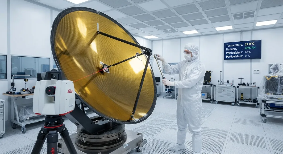
Carbon fiber-reinforced polymer (CFRP) satellite antenna reflectors have become the industry standard for spaceborne communications, Earth observation, and scientific instruments. This article examines the engineering parameters governing surface accuracy and thermal stability, compares solid CFRP versus carbon fiber mesh alternatives, and provides material selection guidance for antenna reflector applications across LEO to GEO orbital regimes.
Introduction: The Role of Carbon Fiber in Space Antennas
Satellite antenna reflectors are among the most demanding applications of carbon fiber composite materials in the space industry. A reflector's ability to maintain its precise parabolic or shaped contour under the extreme thermal cycling conditions of orbit — from -180°C in eclipse to +150°C in direct sunlight — directly determines the antenna gain, beam pattern, and overall communication link performance. Over the past three decades, carbon fiber-reinforced polymer (CFRP) has progressively replaced aluminum, beryllium, and invar as the primary material for spaceborne antenna reflectors, driven by its unique combination of high specific stiffness, near-zero coefficient of thermal expansion (CTE), and design flexibility for complex geometries.
The global market for satellite antenna reflectors is projected to grow from $1.8 billion in 2025 to $3.4 billion by 2032, driven by the expansion of LEO broadband constellations (Starlink, OneWeb, Kuiper), GEO communications satellite replenishment, and the increasing demand for high-resolution Earth observation and synthetic aperture radar (SAR) satellites. Carbon fiber materials account for approximately 55-60% of the structural mass of a typical reflector assembly, with the balance consisting of metallic coatings, support struts, and deployment mechanisms. Selecting the correct carbon fiber material system, layup sequence, and structural concept (solid vs. mesh) is critical to meeting the stringent surface accuracy and thermal stability requirements of each mission profile.
Surface Accuracy Requirements
The surface accuracy of a satellite antenna reflector is quantified by the root-mean-square (RMS) deviation of the actual surface from the ideal design contour, typically expressed in millimeters or micrometers. The required accuracy scales directly with the operating frequency: higher frequencies require proportionally tighter tolerances because surface errors introduce phase errors in the reflected wavefront that reduce antenna gain and increase side lobe levels. The widely accepted Ruze criterion states that the gain reduction due to random surface errors is acceptable when the RMS error is less than λ/50, where λ is the operating wavelength. For practical antenna design, manufacturers typically target RMS surface errors of λ/50 to λ/100 for prime focus and Cassegrain reflector configurations.
| Frequency Band | Frequency Range | Wavelength (λ) | Required RMS Accuracy (λ/50) | Typical Application |
|---|---|---|---|---|
| L-band | 1-2 GHz | 150-300 mm | 3.0-6.0 mm | Mobile satellite communications, GPS |
| C-band | 4-8 GHz | 37.5-75 mm | 0.75-1.5 mm | Fixed satellite service, VSAT |
| Ku-band | 12-18 GHz | 16.7-25 mm | 0.33-0.50 mm | Direct-to-home TV, broadband |
| K-band | 18-27 GHz | 11.1-16.7 mm | 0.22-0.33 mm | Satellite backhaul, Earth observation |
| Ka-band | 27-40 GHz | 7.5-11.1 mm | 0.15-0.22 mm | High-throughput satellites, 5G NTN |
| Q/V-band | 40-75 GHz | 4.0-7.5 mm | 0.08-0.15 mm | Next-gen VHTS, feeder links |
For Ka-band and above, achieving the required RMS surface accuracy of 0.15-0.22 mm (150-220 μm) presents significant manufacturing challenges. The as-manufactured surface accuracy of a CFRP reflector is influenced by: (1) mold surface quality and dimensional stability during cure; (2) resin shrinkage during curing; (3) ply thickness uniformity and fiber placement accuracy; (4) post-cure warpage due to residual stress; and (5) coating thickness variability. State-of-the-art manufacturing processes using Invar molds with precision CNC machining achieve mold surface accuracies of ±10 μm, and CFRP reflectors can be consistently manufactured to RMS surface errors of 50-120 μm for development programs and 100-200 μm for production programs using high-modulus pitch-based carbon fibers.
Thermal Stability in Orbital Environments
The orbital thermal environment is the most demanding aspect of spacecraft design for CFRP structures. A satellite in GEO experiences approximately 90 minutes of sunlight followed by 90 minutes of eclipse during equinox seasons, cycling the reflector temperature between -180°C and +150°C every orbit. For LEO satellites in Sun-synchronous orbits, the thermal cycling frequency is even higher — up to 16 cycles per day. Under these conditions, any mismatch in the coefficient of thermal expansion (CTE) between the reflector substrate and the metallic coating or mounting structure leads to distortion of the reflecting surface, degrading antenna performance.
| Carbon Fiber Type | Tensile Modulus (GPa) | CTE (ppm/K) Fiber Direction | CTE (ppm/K) Transverse | Thermal Conductivity (W/m·K) | Density (g/cm³) |
|---|---|---|---|---|---|
| Standard Modulus (T300-grade) | 230 | -0.4 to -0.7 | 8-12 | 8-12 | 1.76 |
| Intermediate Modulus (T800-grade) | 295 | -0.7 to -1.0 | 7-10 | 15-25 | 1.80 |
| High Modulus (M40J-grade) | 390 | -1.0 to -1.3 | 5-8 | 40-60 | 1.77 |
| Ultra-High Modulus (K13D/UHM-grade pitch) | 790-935 | -1.2 to -1.5 | 3-5 | 150-300 | 2.15 |
| Pitch-based (K13C2U, YSH-70A) | 620-780 | -1.0 to -1.4 | 4-6 | 120-250 | 2.10 |
The key design parameter for thermal stability is achieving a near-zero CTE in the reflector substrate. Quasi-isotropic laminate layups ([0/±60] or [0/±45/90] families) of high-modulus carbon fiber/epoxy composites typically produce in-plane CTE values of +0.2 to -0.3 ppm/K, which can be tuned to match the CTE of the metallic coating layer (typically 0.5-2.0 μm of vapor-deposited aluminum or silver). For ultra-stable reflectors used in SAR and high-resolution Earth observation missions, research programs have demonstrated laminate CTE control to within ±0.02 ppm/K through careful selection of fiber type, ply orientation, and cure cycle optimization. The high thermal conductivity of pitch-based carbon fibers (150-300 W/m·K, exceeding that of aluminum at 237 W/m·K) provides the additional benefit of rapid heat spreading across the reflector surface, minimizing temperature gradients that would otherwise cause distortion.
Solid CFRP vs. Carbon Fiber Mesh Reflectors
The choice between a solid CFRP reflector shell and a carbon fiber mesh reflector depends primarily on the operating frequency, reflector diameter, launch mass constraints, and stowage volume requirements. Solid CFRP reflectors consist of a thin composite shell (typically 0.5-3.0 mm thick) supported by a CFRP or aluminum honeycomb backing structure, with a metallic reflective coating applied to the front surface. They offer the highest surface accuracy and are the standard choice for frequencies above 10 GHz where RMS errors below 0.5 mm are required. However, for large reflectors exceeding 5 meters in diameter, the mass of a solid CFRP shell becomes prohibitive, and the stowed volume conflicts with launch vehicle fairing dimensions.
- Solid CFRP Reflectors: Achieve RMS surface accuracy of 25-150 μm; suitable for all frequency bands up to Q/V-band; mass per unit area of 3-8 kg/m² for a complete assembly; diameter range 0.3-5.0 m (monolithic); proven on thousands of missions; mature manufacturing base with established qualification protocols.
- Carbon Fiber Mesh Reflectors (Knitted/ Braided): Achieve RMS surface accuracy of 100-500 μm; suitable for L-band through Ku-band (up to 18 GHz); mass per unit area of 0.5-2.0 kg/m²; diameter range 3-25 m (deployable); stowed volume ratio typically 5:1 to 15:1; deployed via mechanical, pneumatic, or shape-memory mechanisms.
- Hybrid Approaches: Multi-section rigid panels (3-6 segments) with precision hinges for reflectors 4-12 m in diameter; combine the surface accuracy of solid shells with deployable architecture; used on TerraSAR-X, Sentinel-1 SAR antennas; RMS accuracy 100-300 μm at Ku-band.
- Tensioned Membrane Reflectors: Carbon fiber-reinforced membrane (25-100 μm thick) tensioned over a CFRP or metallic rim; surface accuracy 200-1000 μm; lowest mass option at 0.1-0.5 kg/m²; suitable for L-band through C-band applications; demonstrated on the NASA Deep Space Network test articles.
For LEO broadband constellation operators deploying hundreds to thousands of satellites, mass and stowage efficiency often outweigh absolute surface accuracy. Mesh reflectors with knitted carbon fiber tricot fabric (typically 3-12K tow, 0.5-2.0 mm stitch pitch) coated with vapor-deposited aluminum or silver provide an attractive balance of mass (0.5-2.0 kg/m²), stowed volume, and RF performance. The knitted carbon fiber substrate offers the necessary electrical conductivity for the reflective coating and provides mechanical compliance for folding and deployment. The surface accuracy of mesh reflectors is governed by the tension distribution in the knitted fabric and the precision of the supporting rim structure, rather than by the composite shell manufacturing tolerances.
Material Selection Guidelines
The selection of the optimal carbon fiber material system for a satellite antenna reflector involves a multi-parameter trade-off that must be evaluated for each specific mission. Pitch-based ultra-high modulus fibers (K13D, YSH-70A class) offer the best combination of near-zero CTE and high thermal conductivity but at significantly higher cost ($500-2,000/kg vs. $30-80/kg for PAN-based high-modulus fibers) and lower strain-to-failure (0.3-0.5% vs. 0.8-1.5% for PAN-based fibers). For programs where cost is a primary driver, PAN-based high-modulus fibers (M40J, M55J class) provide adequate thermal stability for L-band through Ka-band applications at $80-200/kg. Intermediate modulus fibers (T800, IM7 class) are suitable for L-band through Ku-band reflectors where surface accuracy requirements are less stringent, offering the best balance of mechanical properties and cost.
| Application Class | Recommended Fiber Type | Laminate Layup Strategy | Coating System | Typical RMS Accuracy |
|---|---|---|---|---|
| GEO Comms (Ku/Ka-band) | High Modulus PAN (M40J/M55J) | Quasi-isotropic, symmetric [0/±45/90]₂s | Vapor-deposited Al (1.0-2.0 μm) | 50-120 μm |
| GEO Comms (Q/V-band) | Ultra-High Modulus Pitch (K13D/YSH-70A) | Optimized quasi-isotropic with ply angle tuning | Vapor-deposited Ag + protective SiO₂ | 25-80 μm |
| LEO Broadband (Ku-band) | Intermediate/High Modulus (T800/M40J) | Thin shell (0.5-1.0 mm), unbalanced for CTE | Vapor-deposited Al or mesh coating | 100-200 μm |
| SAR Antenna (C/X-band) | High Modulus PAN (M40J) | Multi-segment rigid panels, precision hinges | Vapor-deposited Al (2.0-3.0 μm) | 100-300 μm |
| Large Deployable (L/S-band) | Standard Modulus (T300) for mesh knitting | Knitted tricot fabric, 3-12K tow | Vapor-deposited Ag + polymer overcoat | 200-500 μm |
FAQ
Why is carbon fiber preferred over aluminum for satellite antenna reflectors?
Carbon fiber composites offer three decisive advantages over aluminum for spaceborne reflectors: (1) Near-zero coefficient of thermal expansion — CFRP laminates can be engineered to CTE values of ±0.3 ppm/K or better, compared to aluminum's 23.1 ppm/K, dramatically reducing thermal distortion in orbit; (2) Higher specific stiffness — carbon fiber's specific modulus (modulus/density ratio) of 130-450 MN·m/kg surpasses aluminum's 26 MN·m/kg, enabling lighter, stiffer reflector shells that maintain their shape under launch vibration and on-orbit thermal loads; and (3) Flexibility in CTE tailoring — through laminate design, the CTE can be matched to metallic coatings and mounting structures, minimizing bi-metallic bending effects that plague aluminum reflectors with reflective coatings.
How does YonXian CarbonFiber support satellite antenna reflector manufacturing?
YongXian CarbonFiber supplies a comprehensive range of carbon fiber materials qualified for space applications, including high-modulus PAN-based fibers (230-440 GPa modulus range) and ultra-high modulus pitch-based fibers (up to 900 GPa). Our products are available with space-grade epoxy sizing compatible with cyanate ester and epoxy resin systems commonly used in reflector manufacturing. We provide full material characterization data including CTE measurements per ASTM E831, thermal conductivity per ASTM E1461, and micro-CT for void content analysis. Our technical team offers laminate design support for CTE optimization and ply layup definition tailored to your specific reflector geometry and orbital environment. Contact our aerospace division for material qualification documentation and sample requests.
What is the maximum diameter achievable for a monolithic CFRP reflector?
The maximum monolithic (single-piece) CFRP reflector diameter is primarily constrained by autoclave size and launch vehicle fairing dimensions. The largest production autoclaves in the composites industry have usable diameters of 5-8 meters (e.g., ASC Process Systems mega-autoclaves at 8.5 m diameter), limiting monolithic CFRP reflectors to approximately 5 meters in diameter for high-accuracy applications. Beyond this size, either segmented rigid panel designs (3-6 panels) or deployable mesh/umbrella concepts are used. For reference, the James Webb Space Telescope's 6.5 m primary mirror uses 18 hexagonal beryllium segments, while large deployable antenna reflectors for mobile satellite services (e.g., TerreStar's 18 m reflector) use knitted carbon fiber mesh over a deployable CFRP truss structure. The choice between monolithic, segmented, and mesh architectures is a fundamental system-level trade-off involving launch vehicle selection, deployment mechanism complexity, and cost.
Part of topic
Related Articles
- Carbon Fiber Mooring for Floating Offshore Wind: Fatigue and Corrosion in Deep Water
- Carbon Fiber Bicycle Frame Optimization: Layup Design and Manufacturing for Competitive Racing
- Carbon Fiber CFRP Retrofit for Infrastructure: Bridge and Building Seismic Strengthening
- Carbon Fiber Medical Imaging Equipment: Lightweight Gantry and Couch Structures for MRI/CT
- Carbon Fiber EV Battery Enclosures: Crash Safety and Electromagnetic Shielding Design
- Carbon Fiber Structures for Low-Altitude Economy: UAV Airframes and eVTOL Components
Interested in Our Products?
Contact our team for competitive pricing and technical specifications.
Get a QuoteRelated Products

Carbon fiber standard plate-3k stripe
Lightweight, ultra-rigid standard sheets for drone fuselages, robot housings, facades and structural applications.

Carbon Fiber Plate — 3K Twill T700 3.0mm
Medium-thickness 3.0mm carbon fiber plate offering significantly higher load capacity while maintaining attractive 3K twill finish. Suitable for structural brackets, reinforcement plates, and load-bearing panels.

Carbon Fiber Plate — 3K Twill T700 1.5mm
Thin 1.5mm carbon fiber plate with 3K twill weave surface. Lightweight and stiff, commonly used for covers, panels, drone bodies, and applications requiring a premium aesthetic appearance.

Square Carbon Fiber Tube — 3K Twill T700
Square cross-section carbon fiber tube manufactured with 3K twill weave for torsional strength. Preferred for structural frames, trusses, and support columns where rectangular geometry offers design flexibility.

Carbon Fiber Plate — UD Unidirectional T700
Unidirectional carbon fiber plate with all fibers oriented in a single direction for maximum strength along the fiber axis. Essential for structural reinforcements, splints, and applications where load direction is predictable.