
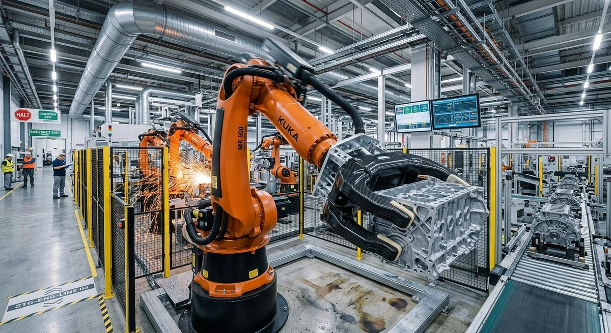
Technical design guide for carbon fiber robotic grippers and end effectors — comparing CF to aluminum and steel across weight, stiffness, cycle time, and payload efficiency for automation applications.
Carbon Fiber Grippers and End Effectors: Engineering for Performance Automation
In modern industrial robotics, the end effector is the interface between the robot arm and the workpiece — and often the bottleneck for throughput, precision, and energy efficiency. A robot is only as fast and accurate as its end effector allows. While traditional end effectors are machined from aluminum 6061-T6 or steel alloys, carbon fiber reinforced polymer (CFRP) has emerged as the superior material for a growing range of automation applications. This article provides design engineers and automation buyers with technical data, comparative analysis, and design guidelines for implementing CFRP grippers and end effectors in production environments.
The Case for Carbon Fiber in End Effector Design
The fundamental advantage of carbon fiber in end effector applications stems from its specific stiffness — the ratio of elastic modulus to density. A standard-modulus unidirectional CFRP laminate (Vf = 60%) offers a specific stiffness of approximately 133 GPa/(g/cm³), compared to 26 for aluminum 6061 and 26 for steel. This 5× advantage in specific stiffness means that for equivalent structural performance, a carbon fiber end effector can be designed at 70–80% lower mass than its aluminum counterpart. The practical implications for industrial robotics are substantial:
- Higher payload utilization: For a typical 6-axis industrial robot (payload capacity 10–50 kg), every kilogram saved on the end effector translates directly to additional payload capacity for the workpiece. A CFRP gripper weighing 1.5 kg instead of 5.5 kg (aluminum) on a 20 kg robot frees 4 kg of payload — a 20% increase in effective capacity.
- Reduced inertia and improved cycle time: Lower mass means lower rotational inertia at the wrist joint. Simulation data from KUKA and Fanuc show that reducing end effector mass by 60% yields cycle time reductions of 15–25% for pick-and-place operations with path lengths exceeding 1 meter.
- Vibration damping: CFRP exhibits 3–5× higher inherent damping than aluminum 6061-T6, reducing settling time after high-speed positioning by 30–50%. This is critical for precision assembly operations (electronic component placement, optical alignment) where residual vibration directly impacts throughput.
- Thermal stability: Carbon fiber's near-zero CTE (−1 to 0 ×10⁻⁶/°C) versus aluminum's 23 ×10⁻⁶/°C eliminates thermal drift in end effector positioning — essential for applications with temperature variations >5°C during production shifts.
Material Comparison: CFRP vs. Metal Alternatives
| Property | CFRP Unidirectional (60% Vf) | CFRP Woven Fabric | Aluminum 6061-T6 | Steel 4140 | Titanium Ti-6Al-4V |
|---|---|---|---|---|---|
| Density (g/cm³) | 1.58 | 1.52 | 2.70 | 7.85 | 4.43 |
| Tensile modulus (GPa) | 210 (0° direction) | 65–70 (planar isotropic) | 68.9 | 200 | 114 |
| Specific stiffness (GPa/(g/cm³)) | 133 | 43–46 | 25.5 | 25.5 | 25.7 |
| Yield/tensile strength (MPa) | 1,800–2,400 (0°) | 550–750 | 276 (yield) | 655 (yield) | 880 (yield) |
| CTE (×10⁻⁶/°C) | −1.0 to 0.5 (0°) | 1–3 (planar) | 23.6 | 12.3 | 8.6 |
| Damping coefficient (×10⁻³) | 12–18 | 8–14 | 3–5 | 2–4 | 4–7 |
| Fatigue endurance limit (10⁷ cycles) | 60–70% UTS | 45–55% UTS | 30–40% UTS | 35–45% UTS | 40–50% UTS |
| Relative mass (same stiffness beam) | 0.19× | 0.55× | 1.0× (baseline) | 1.0× | 0.99× |
| Blank material cost ($/kg) | $25–55 | $20–45 | $3–5 | $2–4 | $30–60 |
| Fabrication cost index | 1.5–3.0× (layup + cure) | 1.5–2.5× | 1.0× (CNC) | 1.2–1.5× | 2.0–3.0× |
| Corrosion resistance | Excellent | Excellent | Moderate (anodize required) | Poor (coating required) | Excellent |
Design Considerations for CFRP End Effectors
Fiber Architecture Selection
The anisotropic nature of CFRP demands deliberate fiber architecture design. For end effector applications, the following layup strategies are recommended:
- Primary gripping arms/fingers: Unidirectional tape oriented along the arm axis (0°), combined with ±45° plies (25–35% of total thickness) for torsional stiffness. Recommended layup: [0₃/±45/0₃] for cantilevered gripping fingers.
- Base plates and mounting flanges: Quasi-isotropic layup [0/±45/90]ₛ or woven fabric (2×2 twill, 200–400 gsm) to provide uniform stiffness in all directions for bolt-hole bearing loads.
- Pneumatic cylinder housings: Braided or filament-wound tubular structures (±45° to ±60° winding angle) optimized for internal pressure of 6–8 bar.
- Sensor mounting brackets: Thin (1–2 mm) woven fabric laminates with localized rib stiffeners for dimensional stability.
Metal Insert Integration
CFRP end effectors require metallic inserts for threaded connections, bearing surfaces, and wear zones. The following insert strategies are field-proven in production robotics:
- Bonded threaded inserts — Aerospace-grade epoxy adhesive (e.g., 3M Scotch-Weld DP420, Loctite Hysol 9394) with surface preparation (grit-blast + solvent wipe). Pull-out strength: 2.5–4.5 kN for M6 inserts in 4 mm CFRP. Suitable for non-critical fastening.
- Co-cured metallic bushings — Stainless steel or titanium bushings placed during layup and co-cured with the laminate. Pull-out strength: 5–8 kN for M6. Requires precision fixture tooling. Preferred for high-cycle applications (>500,000 cycles).
- Compression molded threaded studs — Studs molded directly into the CFRP during compression molding. Highest pull-out strength (8–12 kN for M6). Suitable for high-load primary structure connections.
Cycle Time and Throughput Impact
| Application | Aluminum Effector Mass | CFRP Effector Mass | Cycle Time (Al) | Cycle Time (CFRP) | Throughput Gain |
|---|---|---|---|---|---|
| Pick-and-place (1 m reach, 2 kg payload) | 4.8 kg | 1.4 kg | 1.8 s | 1.4 s | +28% |
| Machine tending (1.5 m reach, 8 kg payload) | 8.2 kg | 2.6 kg | 4.2 s | 3.2 s | +31% |
| Palletizing (2 m reach, 25 kg payload) | 15.0 kg | 4.8 kg | 8.5 s | 6.1 s | +39% |
| Precision assembly (0.6 m reach, 1 kg) | 3.2 kg | 1.0 kg | 2.5 s | 1.9 s | +32% |
| Spot welding (1.8 m reach, 12 kg tooling) | 18.5 kg | 5.8 kg | 6.0 s | 4.3 s | +39% |
Total Cost of Ownership Analysis
While the initial cost of a CFRP end effector is typically 1.5–3.0× that of an aluminum equivalent, total cost of ownership analysis over 3 years of continuous production (two shifts/day, 240 days/year) reveals compelling economics:
| Cost Category | Aluminum 6061 End Effector | CFRP End Effector | Delta |
|---|---|---|---|
| Initial fabrication cost | $2,800 | $5,400 | +$2,600 |
| Installation and calibration | $450 | $350 | −$100 |
| Energy cost (3 years, two shifts) | $1,920 | $640 | −$1,280 |
| Maintenance and repair (3 years) | $1,200 | $400 | −$800 |
| Replacement components (3 years) | $900 | $0 (warranty period) | −$900 |
| Downtime cost (3 years, at $120/hr) | $3,600 (30 hours) | $960 (8 hours) | −$2,640 |
| Total 3-Year Cost | $10,870 | $7,750 | −$3,120 (29% savings) |
Frequently Asked Questions
Q: How does CFRP perform in high-temperature manufacturing environments near furnaces, ovens, or welding stations?
A: Standard 120–180°C-cure epoxy matrix CFRP is suitable for ambient temperatures up to 150°C continuous. For applications near furnaces, ovens, or spot welding stations where radiant heat may push local temperatures above 180°C, we recommend high-Tg epoxy CFRP (200°C service) or BMI-based CFRP for sustained exposure up to 260°C. For extreme environments near molten metal (die casting, forging), titanium or ceramic end effectors remain the standard. As a rule, measure the peak temperature at the end effector mounting surface during worst-case production conditions and allow a 30°C safety margin below the laminate's Tg wet.
Q: Can CFRP end effectors withstand the impact loads from gripping irregular or heavy castings?
A: Yes — with appropriate design provisions. For high-impact gripping applications (sand castings, forgings with ±3 mm dimensional variation), we recommend: (1) Woven fabric laminates (2×2 twill, 400–600 gsm) instead of unidirectional tape for improved interlaminar toughness, (2) Thermoplastic polyurethane (TPU) or silicone gripper pads bonded to the CFRP contact surfaces (3–6 mm thickness) for impact distribution, (3) Radiused geometry — avoid sharp internal corners (minimum radius 5 mm, recommended 8 mm for load-bearing structures), (4) Hybrid CFRP-metal construction for critical impact zones, with local titanium or stainless steel wear plates. In a published case study from BMW Group (2025), CFRP grippers handling 35 kg engine block castings at 2.5 m/s approach velocity demonstrated 18-month service life with zero structural failures, compared to 8 months for 6061 aluminum grippers that suffered fatigue cracking at weld joints.
Q: What is the lead time and minimum order quantity for custom CFRP end effectors?
A: Custom CFRP end effector lead times vary by complexity and production method. Compression molded parts (high volume): 8–12 weeks with MOQ of 500–2,000 units per design. Hand layup + autoclave (prototype/low volume): 3–6 weeks with MOQ of 1–20 units. CNC-machined from CFRP plate (one-off): 1–3 weeks, no MOQ. For B2B buyers comparing quotes: request the fabrication method, as it directly impacts both cost and mechanical properties. Compression molding yields the most consistent fiber volume fraction (58–62%) and the tightest dimensional tolerances (±0.1 mm), while hand layup typically achieves 52–58% Vf with ±0.3–0.5 mm tolerances.
Q: How do I specify the fiber architecture in my RFQ to ensure consistent quality?
A: Include the following in your RFQ or technical specification: (1) Fiber type — standard modulus (230 GPa, 12K or 24K tow) vs intermediate modulus (295 GPa, 12K). (2) Resin system — specify Tg requirement (dry/wet), service temperature, and chemical resistance. (3) Fiber volume fraction — specify target Vf and acceptable range (e.g., 58–62% for structural components). (4) Ply orientation sequence — use standard composite notation [0/±45/90]ₛ, include ply count and cured ply thickness. (5) Layup method — hand layup, ATL, AFP, or compression molding. (6) Non-destructive testing requirements — ultrasonic C-scan, thermography, or tap testing as applicable. (7) Surface finish — bag-side finish (typical 0.5–1.0 μm Ra) or machined surface (0.8–3.2 μm Ra).
Q: What are the failure modes of CFRP end effectors and how can they be prevented?
A: The five primary failure modes in CFRP end effectors are: (1) Delamination at bolted joints — prevented by using oversized washers (3× bolt diameter), torque control with ±5% tolerance, and bonded metallic insert plates. (2) Fiber breakout at machined edges — prevented by machining with PCD (polycrystalline diamond) tooling and flood coolant; specify minimum edge distance 3× hole diameter. (3) Impact damage at gripping surfaces — prevented by bonded elastomeric pads and the woven fabric layup strategy described above. (4) Moisture-induced Tg suppression in epoxy systems — prevented by specifying moisture-resistant resin for high-humidity environments (>70% RH) and applying protective gel coat or polyurethane paint. (5) Creep at threaded insert joints under sustained load — prevented by using co-cured or compression-molded inserts rather than bonded-only inserts for static loads exceeding 30% of the fastener proof load.
Part of topic
Related Articles
- Carbon Fiber Mooring for Floating Offshore Wind: Fatigue and Corrosion in Deep Water
- Carbon Fiber Bicycle Frame Optimization: Layup Design and Manufacturing for Competitive Racing
- Carbon Fiber CFRP Retrofit for Infrastructure: Bridge and Building Seismic Strengthening
- Carbon Fiber Medical Imaging Equipment: Lightweight Gantry and Couch Structures for MRI/CT
- Carbon Fiber EV Battery Enclosures: Crash Safety and Electromagnetic Shielding Design
- Carbon Fiber Structures for Low-Altitude Economy: UAV Airframes and eVTOL Components
Interested in Our Products?
Contact our team for competitive pricing and technical specifications.
Get a QuoteRelated Products

Carbon Fiber Plate — 3K Twill T700 1.5mm
Thin 1.5mm carbon fiber plate with 3K twill weave surface. Lightweight and stiff, commonly used for covers, panels, drone bodies, and applications requiring a premium aesthetic appearance.

Carbon fiber standard plate-3k stripe
Lightweight, ultra-rigid standard sheets for drone fuselages, robot housings, facades and structural applications.

Square Carbon Fiber Tube — 3K Twill T700
Square cross-section carbon fiber tube manufactured with 3K twill weave for torsional strength. Preferred for structural frames, trusses, and support columns where rectangular geometry offers design flexibility.

Carbon Fiber Plate — 3K Twill T700 3.0mm
Medium-thickness 3.0mm carbon fiber plate offering significantly higher load capacity while maintaining attractive 3K twill finish. Suitable for structural brackets, reinforcement plates, and load-bearing panels.

Carbon Fiber Plate — UD Unidirectional T700
Unidirectional carbon fiber plate with all fibers oriented in a single direction for maximum strength along the fiber axis. Essential for structural reinforcements, splints, and applications where load direction is predictable.