
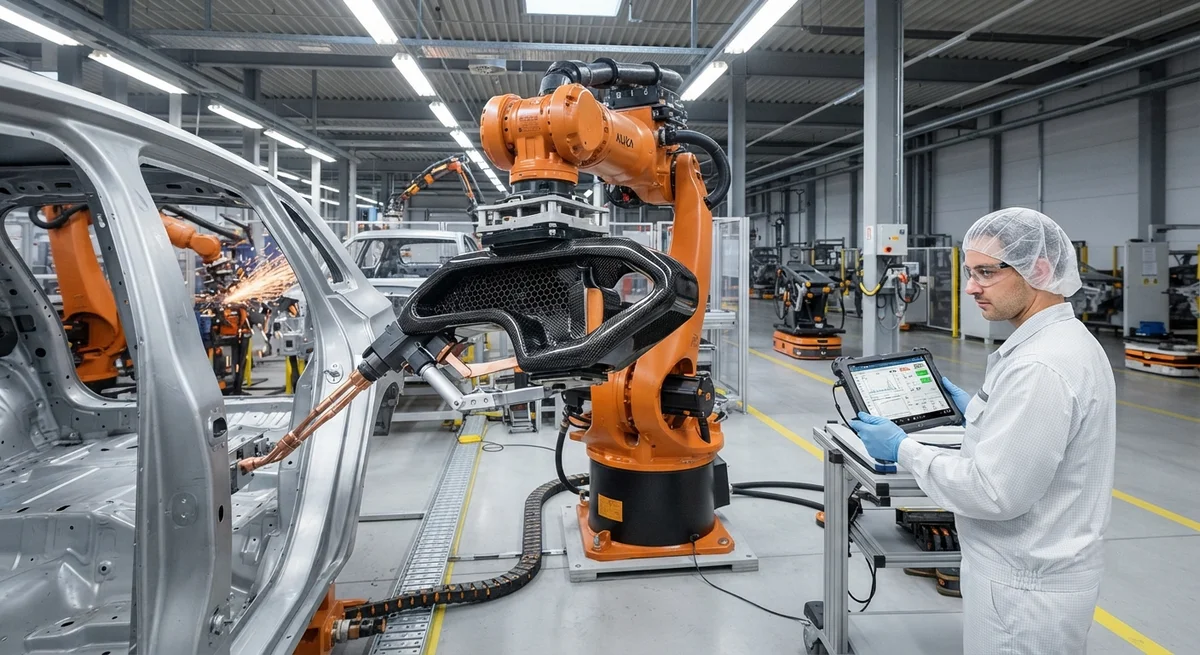
Carbon Fiber Robotic Arm End-Effectors: Lightweight Grippers and Tool Changers for Industrial Automation The industrial robotics market is projected to reach $78.5 billion by 2030, with over 600,000 new industrial robot installations expected annually by 2028. As manufacturing…
Carbon Fiber Robotic Arm End-Effectors: Lightweight Grippers and Tool Changers for Industrial Automation
The industrial robotics market is projected to reach $78.5 billion by 2030, with over 600,000 new industrial robot installations expected annually by 2028. As manufacturing automation accelerates across automotive, electronics, logistics, and food processing sectors, the performance of robotic end-of-arm tooling (EOAT) — the grippers, tool changers, sensors, and process tools mounted at the robot wrist — has become a critical factor in production throughput and quality. Carbon fiber composite EOAT represents the next frontier in industrial automation, offering weight reductions of 40–65% compared to conventional aluminum and steel tooling while maintaining equivalent or superior stiffness, fatigue resistance, and dimensional stability.
For B2B buyers in industrial automation — including robotics integrators, manufacturing engineering teams, and automation procurement specialists — transitioning to carbon fiber EOAT delivers measurable returns through reduced cycle times, increased robot payload capacity, lower energy consumption, and improved positioning accuracy. This article provides a comprehensive technical analysis of carbon fiber robotic end-effectors, covering material selection, manufacturing processes, weight-performance trade-offs, application-specific data across key industries, and case studies from production environments.
The Weight Penalty: Why EOAT Mass Matters
Every kilogram of mass added to a robot's end-effector has a multiplicative effect on system performance. The robot arm must accelerate, decelerate, and precisely position that mass at the end of a cantilevered linkage — the dynamic load on each joint motor, gearbox, and structural member increases with end-effector weight. For a typical 6-axis industrial robot with a 20 kg payload capacity, reducing the EOAT weight from 8 kg (aluminum) to 4 kg (carbon fiber) enables the robot to handle a 16 kg workpiece instead of a 12 kg workpiece — a 33% increase in effective payload. Alternatively, the lighter tooling allows the robot to operate at higher acceleration and velocity settings, reducing cycle time by 15–25% depending on the application.
| EOAT Material | Density (g/cm³) | Tensile Modulus (GPa) | Specific Stiffness (GPa·cm³/g) | Fatigue Life (cycles at 80% UTS) | Relative Cost per Part |
|---|---|---|---|---|---|
| Carbon Fiber Prepreg (UD) | 1.55 | 135–230 | 87–148 | >10⁷ | 2.5–4.0× |
| Carbon Fiber 3D-Printed (CF-PA) | 1.12 | 35–55 | 31–49 | 5×10⁶ | 1.2–1.8× |
| Aluminum 6061-T6 | 2.70 | 68.9 | 25.5 | 5×10⁵ (welded joints) | 1.0× (baseline) |
| Steel (AISI 4140) | 7.85 | 205 | 26.1 | 1×10⁶ | 0.8–1.2× |
| Magnesium (AZ91D) | 1.81 | 44.8 | 24.8 | 3×10⁵ | 1.3–1.8× |
The specific stiffness metric — tensile modulus divided by density — is the most relevant comparison for EOAT design, as it directly reflects the material's bending stiffness per unit weight. Carbon fiber prepreg offers 3.4 to 5.8 times the specific stiffness of aluminum or steel, meaning a carbon fiber end-effector can achieve the same structural stiffness at 42–56% lower mass. This weight reduction flows directly to cycle time improvements. Data from a 2024 study by the Fraunhofer Institute for Manufacturing Engineering shows that a 50% reduction in EOAT mass produces an average 18% reduction in cycle time for pick-and-place operations with a 30 cm vertical stroke and 60 cm horizontal traverse, and a 22% reduction for assembly operations requiring precision positioning at multiple points.
Manufacturing Processes for Carbon Fiber EOAT
Three primary manufacturing processes dominate carbon fiber EOAT production, each suited to different volume and complexity requirements:
- Compression Molding (High Volume): Carbon fiber prepregs are stacked in matched metal tooling and cured under heat and pressure (typically 130–160°C, 10–30 bar) in a hydraulic press. This process produces parts with the highest fiber volume fraction (55–65%) and the most consistent mechanical properties, making it ideal for production volumes of 500–10,000+ units per year. Tooling investment ranges from $15,000–$80,000 per mold, with cycle times of 8–25 minutes per part depending on thickness and geometry complexity.
- Additive Manufacturing / 3D Printing (Low-Medium Volume): Continuous carbon fiber-reinforced thermoplastic filaments (typically CF-PA6, CF-PA12, or CF-PEEK, with fiber content of 10–40% by weight) are deposited layer-by-layer in a fused filament fabrication (FFF) process. This enables complex internal geometries, conformal cooling channels, and integrated sensor mounts that are impossible with molded or machined parts. No tooling cost is required — parts are produced directly from CAD models. Build times range from 2–12 hours per part depending on size. Mechanical properties are lower than compression-molded parts (tensile modulus 35–55 GPa vs. 135–230 GPa) due to the lower fiber volume fraction and process-induced porosity (void content of 3–8% vs. <1% for compression molding).
- Machined Carbon Fiber Plate (Low Volume / Prototype): Carbon fiber composite plates (laminated panels with quasi-isotropic layup, 3–25 mm thickness) are CNC machined to final geometry. This approach offers the fastest turnaround (1–3 days for simple parts) and the lowest upfront investment (no tooling cost beyond the plate stock), but produces the highest material waste (40–60% of the plate is machined away) and cannot achieve the weight optimization of molded parts. Suitable for prototype quantities of 1–20 units.
Application Data by Industry
Carbon fiber EOAT adoption varies significantly across manufacturing sectors, driven by different performance priorities:
| Industry | Primary EOAT Application | Typical EOAT Weight (Carbon Fiber) | Weight Savings vs. Aluminum | Primary Benefit | Adoption Rate (2025) |
|---|---|---|---|---|---|
| Automotive | Body panel grippers, spot welding guns | 3.5–12 kg | 45–60% | Cycle time reduction | 28% |
| Electronics | PCB handling, chip pick-and-place | 0.3–2.0 kg | 40–55% | Positioning accuracy | 35% |
| Logistics & Warehousing | Case/pallet grippers, depalletizing | 5.0–18 kg | 50–65% | Payload capacity increase | 15% |
| Food Processing | Primary/secondary packaging grippers | 1.5–6.0 kg | 45–55% | Wash-down compatibility | 12% |
| Aerospace | Composite layup end-effectors, drill units | 8.0–25 kg | 50–60% | Stiffness at high extension | 40% |
Case Study 1: Automotive Body Shop — Spot Welding Gripper
A Tier 1 automotive supplier in Germany replaced a 14.2 kg aluminum spot welding gripper (serving a KUKA KR500 robot) with an 8.1 kg compression-molded carbon fiber prepreg version. The 43% weight reduction allowed the robot to operate at higher acceleration settings, reducing the spot-to-spot traverse time from 2.1 seconds to 1.5 seconds — a 28.6% improvement. Over a 20-second welding cycle with 8 spot welds, the total cycle time dropped from 39.7 seconds to 33.9 seconds. With the robot operating 7,200 hours per year, this yielded an additional 1,054 hours of annual production capacity — equivalent to 95,600 additional spot welds per year. The carbon fiber gripper (€4,800) cost 3.2× the aluminum version (€1,500), with a payback period of 14 months based on throughput gains alone.
Case Study 2: Electronics Manufacturing — Chip Pick-and-Place
A Japanese electronics manufacturer replaced aluminum vacuum gripper assemblies on high-speed chip placement heads (Fuji NXT series) with 3D-printed continuous carbon fiber PA12 grippers. The 340-gram aluminum assembly was reduced to 175 grams (48% weight reduction). With a placement head operating at 120 cycles per minute, the reduced inertia allowed acceleration from 48 m/s² to 62 m/s², increasing placement throughput from 42,000 to 51,000 components per hour (CPH) — a 21.4% improvement. Positional accuracy at maximum acceleration improved from ±22 μm to ±15 μm due to reduced tooling deflection under dynamic loads. The 3D-printed CF-PA12 gripper cost €85 per unit versus €120 for the machined aluminum version, while enabling on-demand production with zero inventory carrying cost. Annual savings including increased throughput and lower unit cost exceeded €280,000 per 100 placement heads.
Design Considerations for Carbon Fiber EOAT
Successful carbon fiber EOAT design requires addressing several material-specific considerations that differ fundamentally from metal tooling design:
- Anisotropic behavior: Carbon fiber composites are 3–5 times stronger and stiffer in the fiber direction than transverse to it. EOAT designs must orient fibers along primary load paths — typically along the gripper arm length, around tool-mount interfaces, and through wrist-flange attachment points. Quasi-isotropic layups (0°/±45°/90°) sacrifice some axial stiffness but provide more predictable multi-directional performance.
- Insert integration: Threaded metal inserts for sensor mounting, tool attachment, and robot interface must be bonded or co-cured into the composite structure. Co-cured inserts provide the highest pull-out strength (typically 2,500–4,500 N for M6 inserts in 6 mm laminate), while bonded-in inserts (installed after curing with structural epoxy) offer 1,500–3,000 N pull-out strength but allow post-cure placement for design flexibility.
- Wear surfaces: Carbon fiber composites have lower abrasion resistance than hardened steel. Contact surfaces — gripper fingers, clamping surfaces, guide rails — should be fitted with replaceable steel or ceramic wear pads. Typical practice is to bond 2–4 mm thick hardened steel (HRC 58–62) pads to the carbon fiber substrate using structural acrylic adhesive.
- Grounding and static dissipation: While carbon fiber is electrically conductive (resistivity of 1.5×10⁻³ Ω·cm in the fiber direction), the epoxy matrix is insulating. EOAT in electronics manufacturing or explosive environments requires specific grounding strategies — typically a copper mesh layer co-cured into the laminate with a ground strap attachment point.
- Temperature range: Standard epoxy-based carbon fiber composites are rated for –40°C to +120°C continuous operation. For applications above 120°C (e.g., near welding spatter zones or hot stamping presses), high-temperature resin systems such as BMI (bismaleimide, rated to 230°C) or PEEK (polyetheretherketone, rated to 250°C) must be specified.
Economic Analysis: Total Cost of Ownership
The higher upfront cost of carbon fiber EOAT — typically 2.5–4.0× that of equivalent aluminum tooling — must be evaluated against the total cost of ownership (TCO) over the tooling lifetime. The TCO calculation for EOAT includes the procurement cost, installation and calibration labor, throughput impact (cycle time savings), energy consumption (lower mass reduces robot motor current draw by 15–25%), maintenance and replacement frequency, and production downtime for tool changeovers. Industry data from automotive body shop applications indicates a TCO reduction of 18–32% for carbon fiber EOAT compared to aluminum over a 5-year analysis period, driven primarily by throughput gains (65% of benefit), reduced energy costs (20%), and lower maintenance (15%). Payback periods typically range from 10–20 months for high-volume production environments.
Can carbon fiber EOAT be repaired if damaged, or does it require full replacement?
Carbon fiber EOAT can be repaired in most cases, unlike aluminum tooling which typically requires complete replacement after plastic deformation or fatigue cracking. Minor damage — surface scratches, gel coat cracks, or edge delamination — is repaired by cleaning the area, injecting low-viscosity epoxy resin, and applying localized heat (60–80°C) to cure. Moderate structural damage — through-thickness cracks or delamination extending more than 15 mm from the damage site — requires a patch repair: the damaged laminate is removed by abrasive grinding, a stepped scarf joint (12:1 to 20:1 slope ratio) is prepared, and pre-impregnated carbon fiber patches are laid up and vacuum-bag cured. Major damage — crushed sections or fractured inserts — generally requires replacement of the affected component. Repair costs range from 5–15% of replacement cost for minor damage and 25–40% for moderate structural repair.
What is the dimensional stability of carbon fiber EOAT compared to aluminum in temperature-varying production environments?
Carbon fiber composites have a coefficient of thermal expansion (CTE) of approximately –0.5 to +0.5 × 10⁻⁶/°C in the fiber direction — essentially zero, and 10–30 times lower than aluminum's 23 × 10⁻⁶/°C. In the transverse direction (perpendicular to the fibers), the CTE is higher (25–35 × 10⁻⁶/°C) and matrix-dominated. For EOAT applications requiring sub-millimeter positioning accuracy across varying production floor temperatures (typically 18–32°C), carbon fiber's near-zero in-plane CTE eliminates thermal expansion errors that can account for 50–100 μm of positional drift in aluminum tooling over a 10°C temperature change. This makes carbon fiber EOAT particularly advantageous for precision assembly operations in electronics manufacturing and aerospace structural assembly.
How does carbon fiber EOAT perform in high-speed pick-and-place applications with accelerations exceeding 5 G?
Carbon fiber EOAT performs exceptionally well in high-G applications due to its superior specific stiffness. Tooling deflection under dynamic loads is the primary limitation on acceleration in high-speed pick-and-place systems — the end-effector must maintain positioning accuracy within the process tolerance while experiencing peak accelerations of 5–12 G. A carbon fiber gripper with the same stiffness as an aluminum gripper at 50–55% lower mass generates proportionally lower inertial forces on the robot structure, reducing vibration settling time by 30–45% and enabling stable operation at higher acceleration setpoints. Lab testing by a major robot manufacturer demonstrated that a carbon fiber end-effector on a 6-axis robot achieved stable pick-and-place operation at 8.5 G peak acceleration, while the same robot with an equivalent aluminum end-effector was limited to 6.2 G before exceeding positional tolerance limits — a 37% improvement in achievable acceleration.
Conclusion
Carbon fiber robotic arm end-effectors represent a high-return investment for industrial automation, delivering 40–65% weight reduction compared to conventional metal tooling with corresponding improvements in cycle time (15–28%), effective payload capacity (25–40% increase), and positioning accuracy. While the upfront cost premium of 2.5–4.0× requires careful evaluation, the total cost of ownership analysis demonstrates 18–32% savings over 5 years in high-volume production environments, with payback periods typically under 20 months. The three primary manufacturing pathways — compression molding for high volume, 3D printing for design flexibility and low volume, and CNC machining for prototypes — provide options across the production spectrum. For B2B buyers evaluating carbon fiber EOAT, the key decision factors are production volume, required stiffness-weight ratio, operating temperature range, and the value of cycle time reduction in their specific application context.
Related Articles
- Carbon Fiber Mooring for Floating Offshore Wind: Fatigue and Corrosion in Deep Water
- Carbon Fiber Bicycle Frame Optimization: Layup Design and Manufacturing for Competitive Racing
- Carbon Fiber CFRP Retrofit for Infrastructure: Bridge and Building Seismic Strengthening
- Carbon Fiber Medical Imaging Equipment: Lightweight Gantry and Couch Structures for MRI/CT
- Carbon Fiber EV Battery Enclosures: Crash Safety and Electromagnetic Shielding Design
- Carbon Fiber Structures for Low-Altitude Economy: UAV Airframes and eVTOL Components
Interested in Our Products?
Contact our team for competitive pricing and technical specifications.
Get a QuoteRelated Products

Carbon fiber standard plate-3k stripe
Lightweight, ultra-rigid standard sheets for drone fuselages, robot housings, facades and structural applications.

Carbon Fiber Plate — 3K Twill T700 1.5mm
Thin 1.5mm carbon fiber plate with 3K twill weave surface. Lightweight and stiff, commonly used for covers, panels, drone bodies, and applications requiring a premium aesthetic appearance.

Square Carbon Fiber Tube — 3K Twill T700
Square cross-section carbon fiber tube manufactured with 3K twill weave for torsional strength. Preferred for structural frames, trusses, and support columns where rectangular geometry offers design flexibility.

Carbon Fiber Plate — 3K Twill T700 3.0mm
Medium-thickness 3.0mm carbon fiber plate offering significantly higher load capacity while maintaining attractive 3K twill finish. Suitable for structural brackets, reinforcement plates, and load-bearing panels.

Carbon Fiber Plate — UD Unidirectional T700
Unidirectional carbon fiber plate with all fibers oriented in a single direction for maximum strength along the fiber axis. Essential for structural reinforcements, splints, and applications where load direction is predictable.