
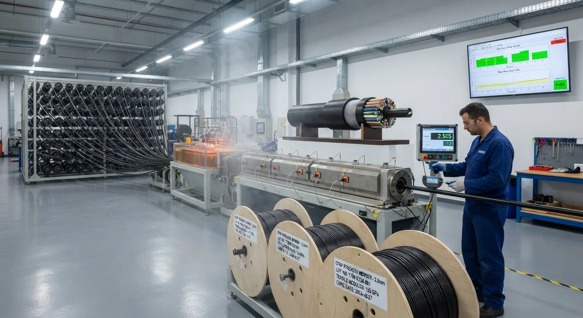
CFRP strength members are replacing traditional steel and aramid in fiber optic cables, offering lower CTE, higher specific stiffness, and corrosion-free operation for long-haul and submarine installations.
Introduction: The Role of Strength Members in Fiber Optic Cables
Fiber optic cables are the backbone of global telecommunications, carrying over 95% of intercontinental data traffic through a network of more than 1.4 million kilometers of submarine cables and millions of kilometers of terrestrial long-haul routes. At the heart of every fiber optic cable is the strength member — a central structural element that provides tensile load-bearing capacity, thermal stability, and protection against installation and environmental stresses. The choice of strength member material directly determines the cable's maximum installation length, operating temperature range, crush resistance, and service life in harsh environments.
Traditional strength member materials include steel wire strands (galvanized or stainless), aramid yarns (Kevlar, Twaron, Technora), and fiberglass reinforced plastics (FRP). Each material carries inherent trade-offs between weight, stiffness, coefficient of thermal expansion (CTE), corrosion resistance, and cost. Over the past decade, carbon fiber reinforced polymer (CFRP) strength members have emerged as a superior alternative for premium cable applications, particularly in long-haul terrestrial routes where low CTE is critical for wavelength-division multiplexing (WDM) system stability, and in submarine cables where zero corrosion and high specific strength enable longer repeaterless spans.
The global fiber optic cable market was valued at USD 12.8 billion in 2025 and is projected to reach USD 19.4 billion by 2031 (7.2% CAGR), driven by 5G backhaul infrastructure expansion, data center interconnectivity, and new submarine cable projects connecting Southeast Asia, Africa, and Latin America. CFRP strength members currently account for approximately 8-10% of the total strength member market by value, with adoption growing at 15-18% annually as cable manufacturers seek differentiation in performance specifications.
Material Comparison: Strength Member Performance
The following table compares the key engineering properties of the four primary strength member materials used in fiber optic cables today. All data represents commercial-grade materials at 23°C unless otherwise noted.
| Property | Steel Wire (Galvanized) | Aramid Yarn (Kevlar 49) | Fiberglass FRP | CFRP (T700S/Epoxy) |
|---|---|---|---|---|
| Tensile strength (MPa) | 1,770–1,960 | 3,620 | 1,100–1,600 | 2,200–2,550 |
| Tensile modulus (GPa) | 200 | 112–131 | 45–55 | 135–150 |
| Density (g/cm3) | 7.85 | 1.44 | 2.0–2.2 | 1.55–1.60 |
| Specific modulus (GPa/(g/cm3)) | 25.5 | 77.8–90.1 | 22–25 | 84–97 |
| CTE (ppm/°C) | 11.5 | −2.0 (axial) | 5.0–6.0 | −0.5 to +0.5 (axial) |
| Corrosion resistance (salt spray) | Poor | Excellent | Good | Excellent |
| Water absorption (24h, %) | 0 | 3.5–4.5 | 0.5–1.5 | 0.1–0.3 |
| Max continuous service temp (°C) | 400 | 150–180 | 180–200 | 150–180 |
| Relative cost per meter | 1.0x (baseline) | 2.5–3.5x | 1.3–1.8x | 3.0–5.0x |
| Cable weight reduction vs. steel (%) | — | 40–55 | 20–35 | 45–60 |
Why CTE Matters in Long-Haul Fiber Optic Cables
In long-haul terrestrial fiber optic cables, the coefficient of thermal expansion of the strength member directly affects optical signal quality. Modern dense wavelength-division multiplexing (DWDM) systems operate with channel spacings as narrow as 50 GHz (0.4 nm), carrying 80–160 channels per fiber pair. A temperature-induced strain of just 0.05% on the optical fiber can cause a wavelength shift of approximately 0.5 pm per °C through the photoelastic effect, leading to channel cross-talk and increased bit-error rates (BER).
Steel strength members have a CTE of approximately 11.5 ppm/°C. For a 100 km cable span experiencing a diurnal temperature variation of 30°C, the steel strength member expands by 34.5 mm, imposing a proportional strain on the buffered optical fibers. CFRP strength members, by contrast, can be engineered with a near-zero or slightly negative axial CTE (−0.5 to +0.5 ppm/°C) by selecting appropriate fiber type (standard modulus vs. high modulus), fiber volume fraction (typically 60–70%), and resin system. This reduces the same thermal expansion to less than 1.5 mm over 100 km, essentially eliminating temperature-induced strain on the optical fibers.
The commercial significance of this advantage is substantial. Cable operators using CFRP-strengthened cables can extend DWDM repeater spans from the typical 80 km (steel-strengthened) to 120–150 km in temperature-stable environments, reducing the number of optical amplifiers and associated power-feeding equipment by 30–40%. For a 1,000 km terrestrial route, this translates to eliminating 3–5 repeater huts at an average cost of USD 180,000–250,000 per hut, resulting in total infrastructure savings of USD 500,000–1,250,000 per route.
Submarine Cable Applications: Corrosion-Free Operation at Depth
Submarine fiber optic cables present the most demanding environment for strength member materials. Cables installed at depths exceeding 4,000 meters must withstand hydrostatic pressure exceeding 40 MPa (5,800 psi), sustained exposure to seawater at 2–4°C, hydrogen evolution from galvanic corrosion, and the risk of shark bites and fishing gear impact in shallower waters. Steel strength members in submarine cables require elaborate corrosion protection — typically a continuous copper tube flooded with petroleum jelly, a polyethylene sheath, and a galvanized steel wire armor layer. Any breach in this multi-layer protection allows seawater ingress, leading to hydrogen generation through galvanic corrosion of the steel, which then diffuses into the optical fibers and causes hydroxyl absorption losses at the 1,383 nm (E-band) wavelength, degrading signal quality within weeks.
CFRP strength members eliminate the galvanic corrosion pathway entirely. Carbon fiber is electrochemically noble in seawater, with a corrosion potential of approximately +0.3 V vs. SCE, compared to −0.6 V for steel. This means CFRP does not corrode, does not generate hydrogen in seawater, and does not require the heavy corrosion protection layers that add 40–80 kg/km to steel-reinforced cables. Submarine cables with CFRP strength members can be designed with simpler outer sheath constructions — typically a single polyethylene layer over the CFRP member and fiber bundles — reducing cable weight by 50–60% compared to equivalent steel-armored designs.
Manufacturing Process and Quality Control
CFRP strength members for fiber optic cables are manufactured using a continuous pultrusion process. Carbon fiber tows — typically Toray T700S 12K or equivalent intermediate modulus fibers — are unwound from creels, passed through a resin bath of modified epoxy or vinyl ester resin, and pulled through a heated die that cures the composite in a continuous profile. Key process parameters include pull speed of 0.5–2.0 m/min, die temperature profile of 120°C (entry) to 200°C (exit) for epoxy systems, fiber volume fraction of 62–68%, diameter tolerance of ±0.05 mm, and typical diameters of 1.0–3.0 mm.
- Short-beam shear strength (ASTM D2344): minimum 50 MPa
- Glass transition temperature (DMA, ASTM D7028): minimum Tg = 140°C (dry)
- Tensile modulus and strength verification per ASTM D3916
- CTE measurement per ASTM E831 (−40°C to +80°C)
- Hydrolytic aging: 28-day immersion in 85°C water, max gain 0.5%
- Creep strain: ≤0.1% at 50% UTS after 1,000h at 60°C
Optical Ground Wire (OPGW) Applications
Optical ground wire (OPGW) combines fiber optic communication with overhead power line shielding. CFRP has been deployed as a central strength member in OPGW designs since 2018, offering ice-load reduction of 40–50%, elimination of corrosion at splice points, and reduced sag at elevated operating temperatures. Field data from Nordic installations (2019–2025) shows zero corrosion-related failures across 1,200 km of installed cable.
Frequently Asked Questions
Q: How does CFRP strength member cost compare to steel over the cable lifecycle?
A: CFRP strength members cost 3–5 times more per meter than galvanized steel. However, lifecycle cost analysis shows CFRP-reinforced cables achieve total cost of ownership parity at 8–12 years of service due to elimination of corrosion-related maintenance, longer repeater spans, and reduced installation costs. For submarine cables with 25-year design life, CFRP provides 15–20% lower lifetime cost.
Q: Is CFRP susceptible to hydrogen damage in submarine environments?
A: Carbon fiber itself does not generate hydrogen in seawater. Unlike steel, which produces hydrogen through galvanic corrosion, CFRP is electrochemically inert in marine environments. The epoxy resin matrix absorbs minimal moisture (0.1–0.3% by weight) and does not undergo hydrolysis at typical seabed temperatures (2–4°C).
Q: Can CFRP strength members be used in existing cable manufacturing lines?
A: Yes, with minor modifications. CFRP rods are supplied in continuous lengths on spools (500–2,000 m per spool) and can be fed through standard cable stranding equipment. The primary modification required is adjustment of the tension control system — CFRP has a higher modulus than steel, so lower tension (typically 50–100 N vs. 200–400 N for steel) is used to avoid over-stressing the fiber.
Conclusion
Carbon fiber strength members represent a significant technological advancement in fiber optic cable design, particularly for long-haul terrestrial routes where CTE stability improves DWDM performance, and for submarine cables where corrosion-free operation extends service life and reduces weight for deeper installation. While the higher material cost of CFRP remains a barrier for price-sensitive commodity cable markets, the total cost of ownership advantages in premium applications are driving adoption at 15–18% annual growth. YongXian CarbonFiber supplies pultruded CFRP rods in diameters from 1.0 to 5.0 mm specifically engineered for fiber optic cable strength member applications, with CTE custom-tuned to match customer cable design requirements.
Related Articles
- Carbon Fiber Mooring for Floating Offshore Wind: Fatigue and Corrosion in Deep Water
- Carbon Fiber Bicycle Frame Optimization: Layup Design and Manufacturing for Competitive Racing
- Carbon Fiber CFRP Retrofit for Infrastructure: Bridge and Building Seismic Strengthening
- Carbon Fiber Medical Imaging Equipment: Lightweight Gantry and Couch Structures for MRI/CT
- Carbon Fiber EV Battery Enclosures: Crash Safety and Electromagnetic Shielding Design
- Carbon Fiber Structures for Low-Altitude Economy: UAV Airframes and eVTOL Components
Interested in Our Products?
Contact our team for competitive pricing and technical specifications.
Get a QuoteRelated Products

Carbon fiber standard plate-3k stripe
Lightweight, ultra-rigid standard sheets for drone fuselages, robot housings, facades and structural applications.

Carbon Fiber Plate — 3K Twill T700 1.5mm
Thin 1.5mm carbon fiber plate with 3K twill weave surface. Lightweight and stiff, commonly used for covers, panels, drone bodies, and applications requiring a premium aesthetic appearance.

Square Carbon Fiber Tube — 3K Twill T700
Square cross-section carbon fiber tube manufactured with 3K twill weave for torsional strength. Preferred for structural frames, trusses, and support columns where rectangular geometry offers design flexibility.

Carbon Fiber Plate — 3K Twill T700 3.0mm
Medium-thickness 3.0mm carbon fiber plate offering significantly higher load capacity while maintaining attractive 3K twill finish. Suitable for structural brackets, reinforcement plates, and load-bearing panels.

Carbon Fiber Plate — UD Unidirectional T700
Unidirectional carbon fiber plate with all fibers oriented in a single direction for maximum strength along the fiber axis. Essential for structural reinforcements, splints, and applications where load direction is predictable.