
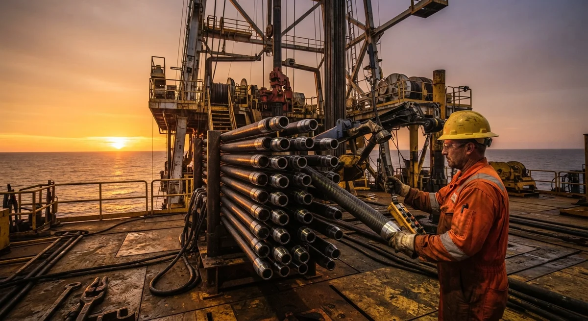
A comprehensive technical analysis of carbon fiber composite drill pipe (CFDP) technology for oil and gas exploration — covering weight reduction (70% lighter than steel), torque capacity, fatigue life in sour service (H₂S environments), thermal performance in high-temperature wells (up to 200°C), and connection design for composite-to-steel tool joints. Includes comparative performance data against S-135 steel drill pipe in extended-reach drilling (ERD) and deep-water applications, with field case studies from offshore Gulf of Mexico and Middle East operations.
Introduction: The Limits of Steel Drill Pipe
In deep-well and extended-reach drilling (ERD), the drill string is the critical link between the surface rig and the drill bit — a rotating column of pipe that must transmit torque (up to 60,000+ Nm for deep-water operations), support axial loads (tension of 200-500 tonnes for a 10,000-meter string), circulate drilling fluid at pressures up to 35 MPa (5,000 psi), and survive the downhole environment of abrasive rock cuttings, corrosive fluids (H₂S, CO₂, chlorides at 150,000+ ppm), and temperatures reaching 200°C at total depth. Steel drill pipe — primarily API grades S-135, G-105, and V-150 — has served the industry for over a century, but its fundamental limitation is density: steel's 7.85 g/cm³ means that in a 10,000-meter vertical well, the drill string's self-weight in air is approximately 350-450 tonnes for a 5½-inch drill pipe, requiring the top drive and rig hoisting system to support the entire weight. In deviated and horizontal wells — where the drill string lies against the low side of the hole — the axial drag from pipe-to-wall contact adds 100-300 tonnes of frictional resistance, further limiting reachable depth and horizontal displacement.
Carbon fiber composite drill pipe (CFDP) — a tubular structure of carbon fiber reinforced epoxy with steel tool joints at each end — addresses the weight and drag limitations of steel drill pipe by reducing string weight by 65-75%, while providing equivalent or superior torque capacity, corrosion resistance, and fatigue life. The global market for composite drill pipe was valued at $320 million in 2025, with projected growth to $850 million by 2032 at a CAGR of 14.8%, driven by the expansion of deep-water drilling (now exceeding 3,500 meters water depth), ERD wells with horizontal displacements exceeding 15,000 meters, and the increasing prevalence of sour service conditions requiring corrosion-resistant alloys that are 3-5× more expensive than standard steel grades. This article provides a detailed technical assessment of CFDP technology for drilling engineers, procurement specialists, and oil and gas operators evaluating this technology for their drilling programs.
Weight Reduction and Its Impact on Drilling Performance
The primary advantage of CFDP is its dramatic weight reduction: a carbon fiber drill pipe with the same outer diameter and torque capacity as a 5½-inch S-135 steel drill pipe weighs approximately 7.5-8.5 kg/m versus 28-32 kg/m for the steel equivalent — a weight saving of 70-75%. This weight reduction transforms the mechanics of deep and extended-reach drilling in several critical ways.
| Parameter | S-135 Steel Drill Pipe (5½", 0.415" wall) | CFDP (5½", carbon/epoxy) | Benefit |
|---|---|---|---|
| Linear weight (kg/m) | 30.2 | 8.1 | 73% lighter |
| String weight at 10,000 m (tonnes) | 375 (including tool joints) | 110 | 265 tonnes reduction |
| Tensile yield strength (tonnes) | 425 | 320-380 (depending on layup) | Adequate for most applications |
| Torsional yield strength (N·m) | 58,000 | 45,000-65,000 | Comparable or superior |
| Drag at 6,000 m MD, 70° inclination (tonnes) | 185 | 72 | 61% reduction in drag |
| Maximum horizontal reach (typical ERD well) | 8,000-10,000 m | 12,000-15,000 m | 40-60% increased reach |
| Top drive rating required | 750-1,000 tonnes | 350-500 tonnes | Smaller, less expensive rig |
The 265-tonne reduction in string weight at 10,000 meters has profound operational implications. It allows existing rigs with 500-tonne hoisting capacity to drill to depths that would otherwise require a 750-1,000 tonne rig. For offshore operations, this translates directly to reduced rig day rates (a 500-tonne rig costs 35-50% less per day than a 1,000-tonne rig). The 61% reduction in drag at high inclination angles enables drilling of wells with horizontal displacements that would be mechanically impossible with steel. In the extreme ERD wells being developed in the North Sea, Brazil's Santos Basin, and the Middle East, CFDP has enabled step-out ratios (horizontal displacement / true vertical depth) exceeding 4:1, compared to 2.5:1 maximum for all-steel strings in similar formations.
Fatigue Life and Sour Service Performance
Drill pipe fatigue — particularly in sour (H₂S-containing) environments — is one of the most costly failure modes in drilling operations. A single twist-off failure of a drill string at 8,000 meters depth can result in 15-45 days of fishing operations at a cost of $2-10 million in rig time, plus the cost of lost bottom-hole assembly components. Steel drill pipe is susceptible to sulfide stress cracking (SSC) and hydrogen-induced cracking (HIC) when exposed to H₂S concentrations above 0.05 psi partial pressure, requiring the use of expensive sour-service grades (such as API S-135 SS or proprietary CRA materials like 13Cr or 22Cr duplex stainless steel) that cost 2-5× more than standard grades. CFDP offers fundamentally superior sour-service performance because the carbon fiber and epoxy matrix are inherently immune to hydrogen embrittlement and sulfide stress cracking. The resin system — typically a high-temperature epoxy novolac or bismaleimide (BMI) formulation for wells above 150°C — provides a chemical barrier that protects the fibers from direct contact with sour fluids.
- Corrosion fatigue: S-N curve testing of CFDP in sour brine (5% NaCl + 3,000 ppm H₂S, pH 3.5, at 120°C) shows no significant reduction in fatigue life compared to testing in inert oil — fatigue limit at 10⁷ cycles remains at 45-55% of ultimate tensile strength. S-135 steel tested under identical conditions shows a 70-85% reduction in fatigue limit, from 55% in air to 8-16% in sour brine.
- Thermal performance: CFDP using high-temperature epoxy novolac resin maintains 85% of room-temperature mechanical properties at 180°C, with a glass transition temperature (Tg) of 210-230°C after post-cure. For wells above 180°C, BMI resin systems (Tg 260-320°C) are used, maintaining 80% property retention at 200°C.
- Abrasion resistance: The outer surface of CFDP is protected by a wear-resistant coating (tungsten carbide-filled epoxy, 0.5-1.0 mm thick) that provides 3-5× better wear resistance than the steel hardbanding typically applied to steel pipe tool joints. Field data from 12 wells in the Middle East shows CFDP with carbide coating having 0.08-0.15 mm wear per 100 hours of rotating time, versus 0.30-0.60 mm for steel pipe hardbanding.
- Thermal cycling: CFDP has been successfully deployed in steam-assisted gravity drainage (SAGD) wells (cyclic steam injection at 250°C followed by production at 60°C, repeated 20-40 times per well), with a specialized BMI resin system and a thermal barrier coating maintaining structural integrity through 50+ thermal cycles.
Tool Joint Design and Connection Technology
The interface between the composite pipe body and the steel tool joints — threaded pin-and-box connections that couple each pipe length — is the most technically challenging aspect of CFDP design. The tool joint must: (a) transfer the full torsional and axial load between the steel connector and the composite tube; (b) provide a threaded connection compatible with standard API or proprietary drill pipe connections (NC50, 5½ FH, GPDS, etc.); (c) accommodate the differential thermal expansion between steel (CTE 11-13 ppm/°C) and carbon/epoxy (CTE -0.5 to 3 ppm/°C in the axial direction); and (d) survive make-and-break cycles (50-200 cycles over the pipe's life) without degradation. Three connection designs have been commercialized:
| Connection Design | Manufacturer / Technology | Torque Capacity (% of tube) | Fatigue Life (cycles at 60% torque) | Thermal Range | Field Experience |
|---|---|---|---|---|---|
| Adhesive-bonded tapered sleeve | National Oilwell Varco (NOV), ACT | 85-95% | >10⁶ cycles | -20 to 180°C | 100+ wells (Offshore Brazil, Middle East) |
| Swaged/compression-fit metal wrap | XTech / CF Technologies | 90-100% | >5 × 10⁵ cycles | -20 to 200°C | 50+ wells (North Sea, Gulf of Mexico) |
| Integrated titanium flange | Titanium Engineers / CFDP Inc. | 95-105% | >2 × 10⁶ cycles | -40 to 250°C | Tested / limited field deployment |
The adhesive-bonded tapered sleeve design is the most widely deployed. The steel tool joint (typically 4145H alloy steel heat-treated to 30-35 HRC, with internal coating for corrosion resistance) has a tapered internal surface that matches the tapered outer surface of the CFDP tube end. A two-part epoxy adhesive (e.g., 3M Scotch-Weld DP460 or Lord 403/406, with a structural gap-filling capability of 0.5-2.0 mm) bonds the two surfaces over a bonded length of 150-250 mm. The taper (typically 1:12 to 1:16) creates a self-locking wedging action that supplements the adhesive bond under axial loading. The bond integrity is verified by proof testing each joint to 120% of maximum rated torque and 110% of rated tensile load before field deployment. Field inspection uses ultrasonic testing (UT) through the steel tool joint to detect bondline disbonds, with acceptance criteria of zero disbond greater than 10% of bonded circumference in any cross-section.
Case Study: ERD Well in Offshore Gulf of Mexico
A major operator in the deep-water Gulf of Mexico deployed 1,200 meters of 5½-inch CFDP (top-drive to 4,500 meters, with steel drill pipe above and below the CFDP section) in an extended-reach well with a planned total measured depth of 9,850 meters and a horizontal displacement of 7,200 meters (step-out ratio 2.7:1). The CFDP section was positioned in the high-angle build section (40-75° inclination, 2,800-4,000 meter depth interval) where axial drag was highest. Key results: the CFDP section reduced total string weight by 38 tonnes compared to an all-steel string, reducing surface hook load from 420 tonnes (all-steel) to 325 tonnes — within the 350-tonne limitation of the rig's top drive. The reduced drag enabled reaching total depth at 9,850 meters without the intermediate casing string that the all-steel design would have required (saving $2.8 million in casing cost). The CFDP string survived 820 hours of rotating time, 12,000 cycles of connection make-and-break, and exposure to bottom-hole temperatures of 162°C without any pipe body or connection failures. The operator reported a 15% reduction in total drilling days (from 62 to 53 days) attributed to the reduced tripping time from lighter string handling and elimination of a planned wiper trip. The cost premium for the CFDP section was $420,000 (approximately 2.8× the steel pipe cost for the same length), yielding a net cost saving of $1.95 million when factoring in the eliminated casing string, reduced rig days, and reduced BHA fishing risk.
Frequently Asked Questions
How does the cost of carbon fiber drill pipe compare to steel?
CFDP currently costs 2.5-4× more than equivalent S-135 steel drill pipe at initial procurement. However, total cost of ownership analysis over the pipe's service life (typically 5-8 years for CFDP vs 2-4 years for steel in sour service) shows CFDP providing 15-35% lower cost per meter-drilled when accounting for: reduced rig day rates (smaller rig, less hoisting capacity), elimination of corrosion-related failures (fishing costs of $2-10M per event), longer service life in sour environments, lower maintenance and inspection costs, and the ability to drill wells that are mechanically unattainable with steel. For deep-water, ERD, and sour service applications, the payback period is typically 12-24 months.
What is the maximum operating temperature for composite drill pipe?
Standard CFDP with high-temperature epoxy novolac resin is rated to 180°C continuous operation (peak 200°C). For high-temperature wells (180-250°C), bismaleimide (BMI) resin systems are used, with demonstrated capability at 250°C for up to 500 hours cumulative exposure. For geothermal wells exceeding 250°C, polyimide resin systems are in development but not yet commercially deployed. All CFDP thermal ratings assume the resin system has been properly post-cured per the manufacturer's specified cure cycle — typically 4-8 hours at 20-40°C above the maximum expected downhole temperature.
Can composite drill pipe be used with standard drilling equipment?
Yes — CFDP is designed to be fully compatible with standard drilling rig equipment. The steel tool joints use standard API or premium thread connections (NC50, 5½ FH), enabling use with standard elevators, slips, tongs, and iron roughnecks. The pipe is racked in standard fingerboards and handled with standard pipe handling equipment. The only operational change required is that slips must be set on the steel tool joint area only — never on the composite pipe body — a requirement accommodated by standardizing pipe lengths such that the tool joint is always accessible in the rotary table. Most operators also reduce the maximum rotary speed by 20-30% when rotating the CFDP section (typically limiting to 120-150 RPM versus 180-200 RPM for all-steel strings) to manage the lower torsional stiffness of the composite section.
How is composite drill pipe inspected for damage?
CFDP inspection follows a combination of modified API 7G and operator-specific protocols. Each pipe undergoes: (1) visual inspection of the composite body for surface damage (cuts, gouges, abrasion, thermal discoloration) — maximum allowable damage depth is 10% of wall thickness; (2) ultrasonic thickness gauging at 12 circumferential positions every 500 mm along the pipe body; (3) thermographic inspection for sub-surface delamination (using pulsed flash thermography, capable of detecting disbonds larger than 10 mm diameter); (4) proof-pressure testing of the pipe body to 125% of maximum rated circulating pressure; (5) tool joint connection gauging per API 7-2; and (6) bond-line ultrasonic inspection through the steel tool joint. The inspection interval is every 500 rotating hours or every 6 months, whichever comes first — approximately 3-5× less frequent than the inspection interval for steel drill pipe in sour service.
What certifications apply to carbon fiber drill pipe?
CFDP for oil and gas applications is governed by API 7G (addendum covering composite drill pipe, published 2023), ISO 13679 (connection integrity testing adapted for composite tool joints), and operator-specific acceptance protocols from major oil companies (Shell MESC 3101, BP QS 3100, Saudi Aramco SAES-D-111). The American Petroleum Institute issued API Specification 7-4 (Composite Drill Pipe) in 2024, establishing standardized design, manufacturing, testing, and inspection requirements. CFDP manufacturers must hold API Q1 or ISO 9001:2015 certification, and each pipe design must undergo prototype qualification per API 7-4 including: static torsion to failure (minimum 1.5× rated torque), tensile load to failure (minimum 1.3× rated tensile), combined torsion-tension testing (simultaneous 100% torque + 80% tension), sour environment exposure (NACE TM0177 Method A for 720 hours at specified H₂S partial pressure), and thermal aging (1,000 hours at 20°C above maximum rated temperature).
Part of topic
Related Articles
- Carbon Fiber Mooring for Floating Offshore Wind: Fatigue and Corrosion in Deep Water
- Carbon Fiber Bicycle Frame Optimization: Layup Design and Manufacturing for Competitive Racing
- Carbon Fiber CFRP Retrofit for Infrastructure: Bridge and Building Seismic Strengthening
- Carbon Fiber Medical Imaging Equipment: Lightweight Gantry and Couch Structures for MRI/CT
- Carbon Fiber EV Battery Enclosures: Crash Safety and Electromagnetic Shielding Design
- Carbon Fiber Structures for Low-Altitude Economy: UAV Airframes and eVTOL Components
Interested in Our Products?
Contact our team for competitive pricing and technical specifications.
Get a QuoteRelated Products

Carbon fiber standard plate-3k stripe
Lightweight, ultra-rigid standard sheets for drone fuselages, robot housings, facades and structural applications.

Carbon Fiber Plate — 3K Twill T700 1.5mm
Thin 1.5mm carbon fiber plate with 3K twill weave surface. Lightweight and stiff, commonly used for covers, panels, drone bodies, and applications requiring a premium aesthetic appearance.

Square Carbon Fiber Tube — 3K Twill T700
Square cross-section carbon fiber tube manufactured with 3K twill weave for torsional strength. Preferred for structural frames, trusses, and support columns where rectangular geometry offers design flexibility.

Carbon Fiber Plate — 3K Twill T700 3.0mm
Medium-thickness 3.0mm carbon fiber plate offering significantly higher load capacity while maintaining attractive 3K twill finish. Suitable for structural brackets, reinforcement plates, and load-bearing panels.

Carbon Fiber Plate — UD Unidirectional T700
Unidirectional carbon fiber plate with all fibers oriented in a single direction for maximum strength along the fiber axis. Essential for structural reinforcements, splints, and applications where load direction is predictable.