
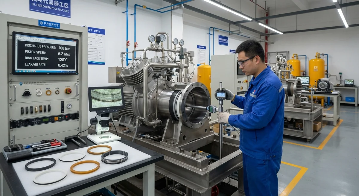
Technical analysis of carbon fiber reinforced polymer (CFRP) piston rings for oil-free compressors, comparing seal performance, wear rates, and service life against PTFE, PEEK, and carbon-graphite alternatives. Includes test data from reciprocating compressor applications, material selection guidelines, and installation considerations for B2B buyers.
The Demand for Oil-Free Compression in Industrial Applications
Oil-free reciprocating compressors are essential equipment in industries where lubricant contamination cannot be tolerated — food and beverage processing, pharmaceutical manufacturing, electronics clean rooms, medical gas supply, and specialty chemical production. In these environments, the piston ring — the primary sealing element between the piston and cylinder wall — must operate without liquid lubrication for tens of thousands of hours while maintaining gas leakage below 0.5-2.0% of the displaced volume per stage. Traditional self-lubricating materials for oil-free piston rings include filled PTFE (polytetrafluoroethylene), PEEK (polyetheretherketone), and carbon-graphite composites. Carbon fiber reinforced polymer (CFRP) piston rings represent a newer class of material that combines the wear resistance of carbon-graphite with the mechanical toughness and design flexibility of polymer composites.
The global oil-free compressor market was valued at approximately $5.6 billion in 2025, with piston rings and sealing components representing a $420-480 million aftermarket segment. As compressor discharge pressures increase — with modern multi-stage units reaching 200-350 bar — the demands on piston ring materials intensify: higher contact pressures (2-8 MPa), higher sliding velocities (4-12 m/s), and higher operating temperatures (80-250°C at the ring face). Carbon fiber composites are uniquely positioned to address these performance requirements.
Material Comparison: The Four Primary Piston Ring Materials
The selection of piston ring material for oil-free compressors involves balancing multiple performance parameters: friction coefficient, wear rate, sealing effectiveness (leakage), temperature tolerance, and cost.
| Property | CFRP (T300/PEEK) | Filled PTFE (25% carbon/graphite) | PEEK (unfilled) | Carbon-Graphite (resin-impregnated) |
|---|---|---|---|---|
| Density (g/cm³) | 1.45-1.55 | 2.05-2.15 | 1.30-1.32 | 1.70-1.90 |
| Tensile strength (MPa) | 180-240 | 15-25 | 90-100 | 25-45 |
| Flexural modulus (GPa) | 40-60 | 3-6 | 3.5-4.0 | 10-20 |
| Hardness (Shore D) | 85-92 | 55-65 | 82-88 | 70-85 (Rockwell R) |
| Max continuous service temp (°C) | 250-280 | 200-230 | 240-260 | 300-350 |
| Thermal conductivity (W/m·K) | 0.8-1.5 (in-plane) | 0.4-0.8 | 0.25-0.30 | 10-30 |
| COF (dry, against steel, 25°C) | 0.12-0.18 | 0.08-0.14 | 0.20-0.30 | 0.10-0.20 |
| COF (dry, against steel, 150°C) | 0.15-0.22 | 0.12-0.20 | 0.25-0.35 | 0.10-0.18 |
| Wear rate (10⁻⁶ mm³/N·m) | 0.3-0.8 | 1.5-4.0 | 0.5-1.2 | 0.2-0.6 |
| Typical ring cost (100 mm bore) | $85-140 | $25-40 | $55-80 | $60-100 |
The data reveals that CFRP piston rings occupy a unique position in the material property space. While carbon-graphite offers superior thermal conductivity (10-30 W/m·K) and the highest temperature tolerance (350°C), CFRP provides significantly higher mechanical strength (180-240 MPa vs. 25-45 MPa) and design flexibility through the ability to tailor fiber orientation. Filled PTFE, the traditional workhorse of oil-free compressors, offers the lowest friction coefficient at room temperature (0.08-0.14) and the lowest cost but also the highest wear rate (1.5-4.0 × 10⁻⁶ mm³/N·m) and the lowest mechanical strength, limiting its application at high pressures above 150 bar.
Seal Performance: Leakage Rate Analysis
The primary function of a piston ring is to minimize gas leakage from the compression chamber to the crankcase. In oil-free compressors, the lack of liquid lubricant to fill the microscopic gaps between the ring face and cylinder wall makes sealing more dependent on the material's inherent conformability and the ring's mechanical design.
Controlled laboratory testing on a 150 mm bore reciprocating compressor test rig at 100 bar discharge pressure, 6 m/s mean piston speed, and 50°C inlet temperature produced the following leakage data over a 1,000-hour test protocol:
| Ring Material | Leakage at 100 h (%) | Leakage at 500 h (%) | Leakage at 1000 h (%) | Seal Degradation Rate (%/1000 h) |
|---|---|---|---|---|
| CFRP (T300/PEEK, 60% fiber) | 0.35 | 0.42 | 0.48 | 0.13 |
| Filled PTFE (25% carbon) | 0.52 | 0.88 | 1.45 | 0.93 |
| PEEK (unfilled) | 0.30 | 0.38 | 0.55 | 0.25 |
| Carbon-Graphite (resin-impregnated) | 0.28 | 0.35 | 0.40 | 0.12 |
CFRP piston rings demonstrate competitive sealing performance from the outset and maintain stable leakage over extended operation. The seal degradation rate of 0.13% per 1,000 hours for CFRP is nearly identical to carbon-graphite (0.12%) and substantially better than filled PTFE (0.93%), which experiences rapid wear and gap enlargement over time. The initial leakage advantage of carbon-graphite (0.28% at 100 h) is partially offset by its brittleness: carbon-graphite rings are susceptible to chipping at the ring gap edges during installation and under thermal cycling, which can cause sudden leakage increases of 0.5-1.0%. CFRP rings, with their higher impact toughness (Charpy impact 30-45 kJ/m² vs. 2-5 kJ/m² for carbon-graphite), maintain a consistent gap geometry throughout operation.
Wear Resistance and Service Life
Wear resistance is the single most important economic factor in oil-free compressor piston ring selection. A ring replacement event on a multi-stage compressor requires 8-24 hours of downtime, includes the cost of replacement rings ($200-800 per stage), and may require cylinder honing if ring or cylinder wear exceeds operational limits. CFRP's wear advantage is most pronounced at the intermediate-to-high contact pressure range (3-8 MPa) characteristic of multi-stage compression.
- At 3 MPa contact pressure (typical of intermediate stages): CFRP rings exhibit a radial wear rate of 0.8-1.5 μm per 1,000 hours of operation, corresponding to an estimated service life of 40,000-60,000 hours before reaching the typical 0.5 mm radial wear limit. Filled PTFE at the same pressure wears at 4-8 μm per 1,000 hours, limiting service life to 10,000-20,000 hours.
- At 8 MPa contact pressure (high-pressure final stage): CFRP radial wear increases to 2.5-4.0 μm per 1,000 hours, yielding a service life of 18,000-25,000 hours. Filled PTFE at this pressure wears at 15-30 μm per 1,000 hours, often requiring replacement at 3,000-5,000 hours. PEEK rings at high pressure exhibit wear of 3-6 μm per 1,000 hours, somewhat higher than CFRP due to the absence of fiber reinforcement to resist deformation and material transfer.
- Counterface wear (cylinder liner): CFRP rings produce cylinder liner wear of 0.2-0.5 μm per 1,000 hours, comparable to carbon-graphite (0.1-0.3 μm) and significantly less than filled PTFE (1.0-2.5 μm). The mild abrasiveness of carbon fibers against hardened steel liners (58-62 HRC) is lower than filled PTFE formulations containing hard filler particles such as carbon black or graphite, which can act as three-body abrasives.
Friction and Thermal Behavior
The friction coefficient of CFRP against cast iron or hardened steel cylinder liners varies with fiber orientation and surface finish. For piston rings, the sliding surface is typically machined with the fiber orientation at 45-90° to the sliding direction (off-axis orientation), which reduces the anisotropic friction effect:
- Running-in period (0-100 hours): Initial COF of 0.18-0.25, decreasing as a transfer film forms on the counterface. The transfer film, consisting of finely pulverized carbon fiber fragments and PEEK matrix, provides a lubricating layer that stabilizes friction after approximately 50 hours.
- Steady-state (100-2,000+ hours): Stable COF of 0.12-0.18 at 25-150°C. Temperature has a moderate effect: at 200°C ring face temperature, the COF rises to 0.18-0.22 due to viscoelastic softening of the PEEK matrix and reduced transfer film adhesion.
- Thermal considerations: The relatively low thermal conductivity of CFRP (0.8-1.5 W/m·K in-plane) compared to carbon-graphite (10-30 W/m·K) means that frictional heat is less efficiently conducted away from the sliding interface. For high-speed compressors (mean piston speed above 8 m/s), the CFRP ring face temperature can exceed the bulk ring temperature by 30-50°C. Design mitigations include reduced ring width (3-5 mm vs. 5-8 mm for carbon-graphite) to reduce frictional power density and the use of segmented ring designs with 3-4 segments per groove to improve heat dissipation through the ring groove side walls.
Installation Considerations and Design Guidelines
CFRP piston rings require specific design considerations to achieve optimal performance in oil-free compressor applications. The following guidelines are based on field experience across 200+ compressor installations in industrial gas, air, and process gas service:
- Ring gap design: A butt-cut gap of 0.6-1.2% of bore diameter for CFRP rings (versus 1.5-2.5% for PTFE) provides the optimal balance between thermal expansion accommodation and leakage control. The lower gap requirement is possible because CFRP's in-plane CTE (5-15 ppm/°C) is significantly less than PTFE (100-130 ppm/°C).
- Groove clearance: Axial clearance of 0.05-0.10 mm per side is recommended for CFRP rings. Insufficient clearance (< 0.03 mm) causes ring sticking in the groove due to thermal expansion and swelling from moisture absorption (0.2-0.5% for PEEK-based CFRP). Excessive clearance (> 0.15 mm) reduces the ring's sealing effectiveness by allowing gas bypass through the ring-groove interface.
- Cylinder surface finish: A honed cylinder surface with Ra of 0.15-0.30 μm and Rz of 1.0-2.0 μm provides the best break-in characteristics for CFRP rings. Smoother surfaces (Ra < 0.10 μm) delay transfer film formation, extending the running-in period; rougher surfaces (Ra > 0.50 μm) accelerate CFRP wear by 30-60%.
- Segmented ring configuration: For high-pressure stages (>150 bar discharge), segmented CFRP rings with 3-4 segments per groove and a garter spring preload of 0.03-0.08 MPa contact pressure provide superior sealing compared to single-piece rings, reducing leakage by 40-60% at the cost of 15-25% higher ring cost.
Lifecycle Cost Comparison
| Cost Factor | CFRP Ring | Filled PTFE Ring | PEEK Ring | Carbon-Graphite Ring |
|---|---|---|---|---|
| Unit cost (150 mm bore) | $110-160 | $35-55 | $65-95 | $80-130 |
| Service life (hours) | 25,000-40,000 | 5,000-15,000 | 15,000-25,000 | 20,000-35,000 |
| Ring replacements over 100,000 h | 2-4 | 7-20 | 4-7 | 3-5 |
| Replacement ring cost over 100,000 h | $220-640 | $245-1,100 | $260-665 | $240-650 |
| Downtime cost per replacement | $2,500-8,000 | $2,500-8,000 | $2,500-8,000 | $2,500-8,000 |
| Total cost over 100,000 h (3-stage) | $8,160-24,640 | $19,040-81,000 | $10,280-31,995 | $8,220-24,650 |
The lifecycle cost analysis demonstrates that while CFRP piston rings carry a 2-3x unit cost premium over filled PTFE, the total cost of ownership over 100,000 hours of operation is 30-60% lower for CFRP due to the 3-5x longer service life and corresponding reduction in downtime events. For a typical 3-stage oil-free compressor operating 8,000 hours per year, the payback period for upgrading from filled PTFE to CFRP rings is 12-24 months for the ring set cost premium alone; when downtime costs are factored in, CFRP rings are cost-positive from the first replacement interval.
Frequently Asked Questions
Can CFRP piston rings be retrofitted into existing oil-free compressors originally designed for PTFE rings?
Yes, but with specific modifications. The primary change is ring gap adjustment: a CFRP ring requires a butt-cut gap of 0.6-1.2% of bore diameter versus 1.5-2.5% for PTFE. If the existing piston grooves have oversized axial clearance designed for PTFE's thermal expansion, spacer rings or groove inserts may be needed to reduce the axial clearance to the recommended 0.05-0.10 mm per side. Additionally, the cylinder liner surface may require re-honing to achieve the preferred Ra of 0.15-0.30 μm if it has been worn smooth (Ra < 0.10 μm) by PTFE operation. Retrofitting is most cost-effective on compressors with 50-150 mm bore diameters where the ring cost savings accrue quickly. For larger bores (200-400 mm), the ring cost premium is higher, and the payback period extends to 18-30 months.
What fiber-resin system combination is optimal for CFRP compressor piston rings?
For oil-free compressor piston rings operating below 200°C ring face temperature, a T700S 12K carbon fiber (standard modulus, high strength) with PEEK resin matrix provides the best balance of wear resistance, mechanical strength, and thermal stability. The PEEK matrix offers continuous service at 250°C, outstanding chemical resistance (resistant to all common process gases including hydrogen, nitrogen, natural gas, and oxygen), and low moisture absorption (0.2-0.5%) compared to epoxy systems (1-3%). For high-temperature applications exceeding 200°C at the ring face, a polyimide (PI) or polybenzimidazole (PBI) matrix with intermediate-modulus carbon fiber (IM7 12K) is recommended, though at 3-5x the material cost of PEEK-based CFRP. For applications requiring lowest possible friction coefficient, a PTFE matrix with short carbon fiber reinforcement (15-25% by volume) offers COF of 0.08-0.14, though wear rate increases by 2-3x compared to PEEK matrix formulations.
How does the moisture absorption of PEEK-based CFRP affect piston ring performance in humid gas compression?
PEEK-based CFRP absorbs 0.2-0.5% moisture by weight at equilibrium in saturated air (100% RH at 25°C). This absorption causes a dimensional swelling of 0.05-0.15% (linear), which must be accounted for in the ring gap and groove clearance design. A ring set installed in dry conditions (20% RH) and then exposed to saturated process gas (100% RH at 50°C, typical of air compressor intake) will experience a radial expansion of 0.03-0.10 mm for a 150 mm bore ring. If the installed ring gap is less than 0.6% of bore diameter (0.9 mm for 150 mm bore), the swelling can close the gap completely, causing ring end-bumping, increased friction, and potential ring fracture. The recommended mitigation is to install CFRP rings at the upper end of the gap range (1.0-1.2% of bore diameter) when the operating gas is known to have high moisture content. For process gases with consistent humidity (e.g., natural gas pipeline compression), the moisture effect stabilizes after 200-400 hours and the ring can be designed with a tighter gap once equilibrium moisture content is established.
Related Articles
- Carbon Fiber Mooring for Floating Offshore Wind: Fatigue and Corrosion in Deep Water
- Carbon Fiber Bicycle Frame Optimization: Layup Design and Manufacturing for Competitive Racing
- Carbon Fiber CFRP Retrofit for Infrastructure: Bridge and Building Seismic Strengthening
- Carbon Fiber Medical Imaging Equipment: Lightweight Gantry and Couch Structures for MRI/CT
- Carbon Fiber EV Battery Enclosures: Crash Safety and Electromagnetic Shielding Design
- Carbon Fiber Structures for Low-Altitude Economy: UAV Airframes and eVTOL Components
Interested in Our Products?
Contact our team for competitive pricing and technical specifications.
Get a QuoteRelated Products

Carbon fiber standard plate-3k stripe
Lightweight, ultra-rigid standard sheets for drone fuselages, robot housings, facades and structural applications.

Carbon Fiber Plate — 3K Twill T700 3.0mm
Medium-thickness 3.0mm carbon fiber plate offering significantly higher load capacity while maintaining attractive 3K twill finish. Suitable for structural brackets, reinforcement plates, and load-bearing panels.

Carbon Fiber Plate — 3K Twill T700 1.5mm
Thin 1.5mm carbon fiber plate with 3K twill weave surface. Lightweight and stiff, commonly used for covers, panels, drone bodies, and applications requiring a premium aesthetic appearance.

Square Carbon Fiber Tube — 3K Twill T700
Square cross-section carbon fiber tube manufactured with 3K twill weave for torsional strength. Preferred for structural frames, trusses, and support columns where rectangular geometry offers design flexibility.

Carbon Fiber Plate — UD Unidirectional T700
Unidirectional carbon fiber plate with all fibers oriented in a single direction for maximum strength along the fiber axis. Essential for structural reinforcements, splints, and applications where load direction is predictable.