
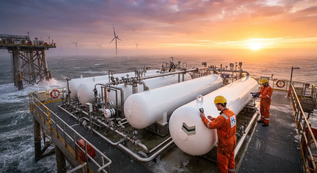
Composite Technology Center (CTC) has developed a four-layer corrosion-resistant coating system for carbon fiber Type IV hydrogen storage tanks in offshore environments. This technical analysis covers the coating architecture — including primer, barrier, UV-resistant, and anti-fouling layers — with detailed performance data from accelerated testing equivalent to 15 years of North Sea conditions. Market projections for offshore hydrogen infrastructure suggest 8,000–12,000 composite storage vessels will be needed by 2035.
CTC Introduces Advanced Corrosion-Resistant Coatings for Offshore Hydrogen Storage
Composite Technology Center (CTC), a leading German research institute specializing in carbon fiber composite manufacturing, has announced the development of a new generation of corrosion-resistant coating systems specifically engineered for carbon fiber composite hydrogen storage tanks deployed in offshore environments. This innovation addresses one of the most persistent challenges facing the offshore hydrogen economy: the combined corrosive effects of saltwater spray, high humidity, UV radiation, and hydrogen permeation on high-pressure composite storage vessels.
Offshore hydrogen storage is critical to the emerging offshore wind-to-hydrogen production model, where electrolyzers located on offshore platforms convert wind-generated electricity into green hydrogen for pipeline transport or ship-based distribution. These storage systems must operate reliably for 20–30 years in the harshest marine environments with minimal maintenance access. CTC's coating technology aims to bridge the gap between the inherent corrosion resistance of carbon fiber composites and the extreme demands of North Sea, Baltic Sea, and Asian offshore operating conditions.
The Corrosion Challenge for Offshore Composite Pressure Vessels
Carbon fiber composites are inherently resistant to electrochemical corrosion — one of their key advantages over steel pressure vessels. However, offshore hydrogen storage introduces unique degradation mechanisms that threaten the long-term integrity of CFRP pressure vessels:
- Salt spray ingress: Chloride ions from seawater can penetrate the epoxy matrix through microcracks, reaching the fiber-matrix interface and causing degradation of the sizing layer that bonds fiber to resin. This reduces interlaminar shear strength by 15–30% over extended exposure.
- UV degradation: The epoxy matrices used in filament-wound composite tanks are susceptible to UV-induced photo-oxidation, which embrittles the surface resin layer and creates pathways for moisture ingress. Topcoat delamination typically begins after 3–5 years of unprotected offshore exposure.
- Hydrogen embrittlement in metallic components: While the CFRP structure itself is immune, the metal boss ends and valve assemblies of Type IV tanks are susceptible to hydrogen embrittlement and galvanic corrosion at the composite-metal interface. CTC's coating system addresses this critical junction.
- Thermal cycling: Offshore environments subject storage vessels to temperature swings from -20°C to +45°C, combined with 95%+ relative humidity. Differential thermal expansion between the composite wall, liner, and coating layers can induce delamination over time.
CTC's Multi-Layer Coating Architecture
The coating system developed by CTC employs a four-layer architecture designed to provide comprehensive protection across all identified degradation mechanisms:
| Layer | Material | Thickness | Primary Function | Performance Target |
|---|---|---|---|---|
| 1. Primer | Epoxy-phenolic with nano-silica reinforcement | 50–80 µm | Chemical bonding to CFRP surface; sealing microcracks | Pull-off adhesion > 5 MPa (ISO 4624) |
| 2. Barrier | Glass flake-filled epoxy | 200–300 µm | Moisture and chloride ion barrier | Water vapor transmission < 0.5 g/m²/day (ASTM E96) |
| 3. UV-resistant | Aliphatic polyurethane with ZnO nanoparticles | 60–100 µm | UV absorption and reflection; gloss retention | Gloss retention > 70% after 3,000 h QUV (ASTM G154) |
| 4. Topcoat (anti-fouling optional) | Polysiloxane-modified polyurethane with biocide (for submerged zones) | 40–60 µm | Anti-fouling, erosion resistance, color stability | No visible macro-fouling after 5 years (ISO 20615) |
CTC reports that the coating system has achieved the following performance metrics in accelerated laboratory testing equivalent to 15 years of North Sea offshore exposure: zero blistering (ASTM D714), no creepage from scribe mark more than 1.5 mm (ASTM D1654), and 92% adhesion retention measured by pull-off testing after 5,000 hours of salt spray exposure (ASTM B117).
Application-Specific Performance Data
CTC's validation program for the coating system included comprehensive testing across multiple offshore-relevant parameters. The key findings are summarized below:
| Test | Standard | Duration | Result (Uncoated CFRP) | Result (CTC-Coated CFRP) |
|---|---|---|---|---|
| Neutral salt spray | ASTM B117 | 4,000 h | Surface pitting, 22% ILSS loss | No visible degradation, 4% ILSS loss |
| Cyclic corrosion (salt + humidity) | ISO 14993 | 1,000 h (100 cycles) | Edge delamination 3–5 mm, microcracking | No edge creep, < 5 microcracks/cm² |
| UV accelerated aging | ASTM G154 (cycle 4) | 3,000 h | Surface yellowing, gloss loss 85% | ΔE < 2 (barely perceptible), gloss retention 74% |
| Hydrogen permeation (coating only) | ISO 15105-2 (manometric) | — | N/A (substrate test: 6×10⁻¹⁴ mol/m·s·Pa) | 3.2×10⁻¹⁴ mol/m·s·Pa (50% reduction) |
| Cathodic disbondment | ASTM G8 | 90 days at −1.5 V vs Ag/AgCl | CFRP-metal interface: disbondment 8–12 mm | Disbondment < 2 mm |
| Rain erosion resistance | ASTM G73 | 2 h at 150 m/s | Surface erosion through to fiber layer | Minor topcoat erosion only |
The interlaminar shear strength (ILSS) retention data is particularly noteworthy. Uncoated CFRP samples exposed to 4,000 hours of neutral salt spray lost 22% of their ILSS — a significant structural degradation. The CTC-coated samples exhibited only 4% ILSS loss, attributed primarily to the primer layer's effectiveness in sealing microcracks that would otherwise serve as pathways for chloride ion ingress.
Offshore Hydrogen Infrastructure: Market Context
The development of corrosion-resistant coating systems comes at a critical juncture for the offshore hydrogen industry. According to the Hydrogen Council, offshore hydrogen production capacity from wind-powered electrolysis is projected to reach 5–7 million tonnes per year by 2035, requiring an estimated 8,000–12,000 high-pressure composite storage vessels for intermediate storage and offloading operations. Each vessel represents a carbon fiber content of 0.5–2.0 tonnes, translating to a total carbon fiber demand of 4,000–24,000 tonnes for offshore hydrogen storage infrastructure alone by 2035.
Key offshore hydrogen projects that will drive demand for coated composite storage include:
- North Sea Energy Hub (Netherlands/UK/Germany): Planned 10 GW offshore wind-to-hydrogen complex with intermediate storage on converted gas platforms. Storage requirement: 500–800 tonnes of hydrogen capacity, requiring 80–120 Type IV tanks at 700 bar.
- H2-Ebner (Germany-Austria): Baltic Sea offshore hydrogen production pilot, targeting 50 MW by 2028 expanding to 2 GW by 2035. Emphasis on subsea hydrogen storage for seasonal buffering.
- POSEIDON (Greece/Cyprus): Mediterranean offshore hydrogen with specialised coating requirements for warmer waters with higher biofouling risk.
- Asian offshore wind-to-hydrogen (Japan, South Korea, Taiwan): Multiple projects in typhoon-prone regions requiring even more robust coating systems with enhanced erosion resistance.
Cost Implications and Economic Analysis
The addition of CTC's coating system adds an estimated 8–15% to the manufactured cost of a Type IV hydrogen storage vessel. However, this incremental cost must be weighed against the cost of premature failure or reduced service life in offshore conditions. Based on CTC's lifecycle cost analysis, the coating system is expected to extend offshore vessel service life from 10–12 years (current uncoated or minimally coated CFRP) to 20–25 years — a 2x improvement that translates to significant total cost of ownership savings.
For a typical 140-liter, 700-bar Type IV tank costing $1,800–$2,200 to manufacture, the coating adds $150–$330 per unit. Over a 20-year service life, the annualized coating cost is $7.50–$16.50 per year, compared to avoided replacement costs of $1,800–$2,200 every 10–12 years. The return on investment is compelling: approximately 5:1 over the vessel's design life.
Frequently Asked Questions
Can existing CFRP hydrogen storage tanks be retrofitted with CTC's coating system?
Yes, CTC's coating system has been designed for both factory-application on new tanks and field-application for retrofitting existing storage vessels. Field application requires careful surface preparation, including abrasive blasting with aluminum oxide (180–240 grit) under controlled humidity conditions (< 60% RH), followed by solvent cleaning to remove any residual contamination. The primer must be applied within 4 hours of surface preparation to prevent re-oxidation of the activated surface. CTC offers a mobile coating application unit that can be deployed to offshore platforms for on-site retrofitting, which is particularly valuable for existing North Sea hydrogen storage installations. Field-applied coatings have demonstrated 85–92% of the adhesion strength of factory-applied coatings in CTC's validation testing, with the primary reduction attributable to less controlled environmental conditions during application.
How does the coating system affect hydrogen permeation through the composite wall?
CTC's multi-layer coating system actually reduces hydrogen permeation through the composite wall by approximately 50%, as demonstrated in manometric testing per ISO 15105-2. The barrier layer (Layer 2, glass flake-filled epoxy) is the primary contributor to this reduction, as the glass flakes create a tortuous path for hydrogen molecules migrating through the coating. However, CTC emphasizes that the coating is not a primary hydrogen barrier — that function remains with the polymer liner and the composite overwrap. The coating's permeation reduction is a secondary benefit that increases overall system safety margins. In the event of a liner leak that allows hydrogen to reach the composite wall, the reduced permeation rate through the coated wall also reduces the rate of hydrogen accumulation in enclosed offshore installation spaces, improving ventilation system effectiveness and reducing explosive gas concentration risks.
What is the expected service life of the coating system in tropical offshore environments (Southeast Asia, Gulf of Mexico)?
CTC has conducted accelerated testing calibrated for tropical offshore conditions using modified ASTM D5894 (combined UV/condensation/salt spray cycling with elevated temperature at 50°C rather than the standard 40°C). Based on these tests, the coating system is projected to maintain protective function for 12–15 years in tropical environments before requiring topcoat renewal. The shorter service life compared to North Sea conditions (20–25 years) is attributable to: higher UV intensity accelerating topcoat degradation, higher average temperatures accelerating chemical diffusion rates in the polymeric coating layers, and increased biofouling pressure requiring more aggressive anti-fouling agents or more frequent cleaning cycles. CTC recommends that tropical offshore installations include a planned topcoat renewal at year 12, which can be performed in-situ using the company's field maintenance system. The primer and barrier layers remain intact through two topcoat renewal cycles, meaning the full coating system lifecycle spans 25–30 years before complete strip and re-application is needed.
Part of topic
Related Articles
- Carbon Fiber Mooring for Floating Offshore Wind: Fatigue and Corrosion in Deep Water
- Carbon Fiber Bicycle Frame Optimization: Layup Design and Manufacturing for Competitive Racing
- Carbon Fiber CFRP Retrofit for Infrastructure: Bridge and Building Seismic Strengthening
- Carbon Fiber Medical Imaging Equipment: Lightweight Gantry and Couch Structures for MRI/CT
- Carbon Fiber EV Battery Enclosures: Crash Safety and Electromagnetic Shielding Design
- Carbon Fiber Structures for Low-Altitude Economy: UAV Airframes and eVTOL Components
Interested in Our Products?
Contact our team for competitive pricing and technical specifications.
Get a QuoteRelated Products

Carbon fiber standard plate-3k stripe
Lightweight, ultra-rigid standard sheets for drone fuselages, robot housings, facades and structural applications.

Carbon Fiber Plate — 3K Twill T700 1.5mm
Thin 1.5mm carbon fiber plate with 3K twill weave surface. Lightweight and stiff, commonly used for covers, panels, drone bodies, and applications requiring a premium aesthetic appearance.

Square Carbon Fiber Tube — 3K Twill T700
Square cross-section carbon fiber tube manufactured with 3K twill weave for torsional strength. Preferred for structural frames, trusses, and support columns where rectangular geometry offers design flexibility.

Carbon Fiber Plate — 3K Twill T700 3.0mm
Medium-thickness 3.0mm carbon fiber plate offering significantly higher load capacity while maintaining attractive 3K twill finish. Suitable for structural brackets, reinforcement plates, and load-bearing panels.

Carbon Fiber Plate — UD Unidirectional T700
Unidirectional carbon fiber plate with all fibers oriented in a single direction for maximum strength along the fiber axis. Essential for structural reinforcements, splints, and applications where load direction is predictable.